9-16 C70 CAPACITOR BANK PROTECTION AND CONTROL SYSTEM – INSTRUCTION MANUAL
OVERVIEW CHAPTER 9: THEORY OF OPERATION
9
9.1.6.2 Balanced case
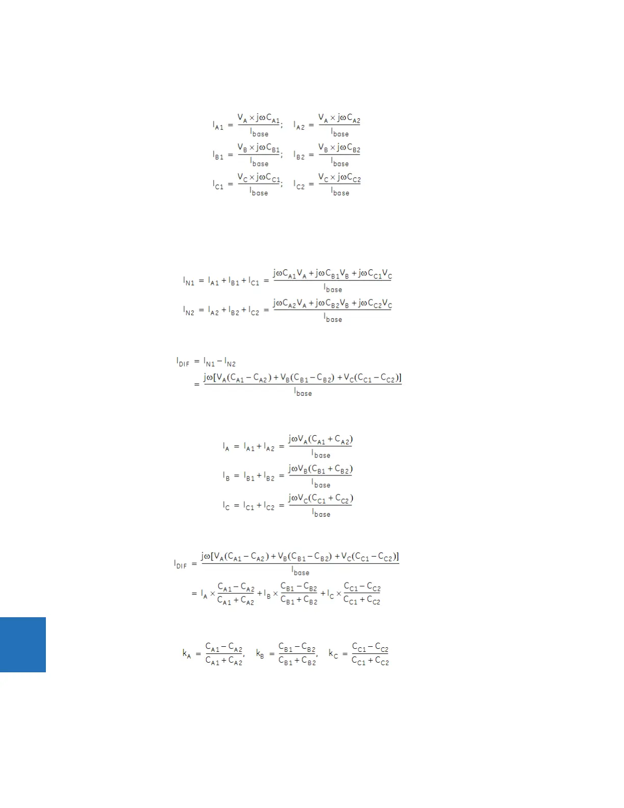
The currents in the neutral current unbalance protection are driven by the individual admittances in each string:
Eq. 9-56
In these equations, I
base
represents the differential CT primary current rating, inserted here to put the string currents on the
same per-unit base used by the relay. Voltages are in primary volts, capacitances in Farads, and frequency in radians per
second.
The two neutral currents can be derived from these equations, as follows:
Eq. 9-57
The differential current is the vector difference between the two currents. By subtracting I
N2
from I
N1
, one obtains:
Eq. 9-58
At the same time the total currents in each phase are driven by the total admittance of the two banks in each phase:
Eq. 9-59
Inserting the equations above into equation 9.58 so as to eliminate the voltages:
Eq. 9-60
Label k
A
, k
B
, and k
C
as follows:
Eq. 9-61