3-20 C70 CAPACITOR BANK PROTECTION AND CONTROL SYSTEM – INSTRUCTION MANUAL
WIRING CHAPTER 3: INSTALLATION
3
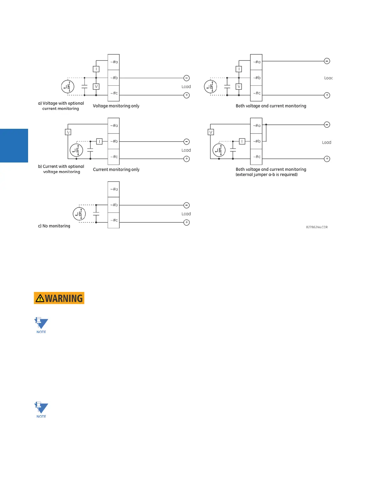
Figure 3-18: Form-A and solid-state contact outputs with voltage and current monitoring
The operation of voltage and current monitors is reflected with the corresponding FlexLogic operands (CONT OP # VON, CONT
OP # VOFF, and CONT OP # ION) that can be used in protection, control, and alarm logic. The typical application of the voltage
monitor is breaker trip circuit integrity monitoring; a typical application of the current monitor is seal-in of the control
command.
See the Digital Elements section of chapter 5 for an example of how form-A and solid-state relay contacts can be applied
for breaker trip circuit integrity monitoring.
Consider relay contacts unsafe to touch when the unit is energized. Death or serious injury can
result from touching live relay contacts.
USE OF FORM-A AND SOLID-STATE RELAY OUTPUTS IN HIGH-IMPEDANCE CIRCUITS
For form-A and solid-state relay output contacts internally equipped with a voltage measuring circuit across the
contact, the circuit has an impedance that can cause a problem when used in conjunction with external high-input
impedance monitoring equipment, such as modern relay test set trigger circuits. These monitoring circuits can
continue to read the form-A contact as being closed after it has closed and subsequently opened, when measured
as an impedance.
The solution is to use the voltage measuring trigger input of the relay test set, and connect the form-A contact
through a voltage-dropping resistor to a DC voltage source. If the 48 V DC output of the power supply is used as a
source, a 500 Ω, 10 W resistor is appropriate. In this configuration, the voltage across either the form-A contact or
the resistor can be used to monitor the state of the output.
Where a tilde “~” symbol appears, substitute the slot position of the module. Where a number sign “#” appears,
substitute the contact number.