CHAPTER 3: INSTALLATION WIRING
C70 CAPACITOR BANK PROTECTION AND CONTROL SYSTEM – INSTRUCTION MANUAL 3-21
3
For high-density input/output modules 6W and 6X, use the following guidelines to connect:
• 12 to 24 AWG (3.3 mm
2
to 0.2 mm
2
), single wire termination
• 16 to 24 AWG (1.31 mm
2
to 0.2 mm
2
), multiple wire termination with matching wire sizes and stranding. Two wires
maximum per circuit.
• Suggested wiring screw tightening torque is a minimum 4.43 in-lb (0.5 Nm) and maximum 5.31 in-lb (0.6 Nm)
• Minimum suggested temperature rating for the conductors is 75°C
• Wire type: copper
• Do not use with SL power supply module
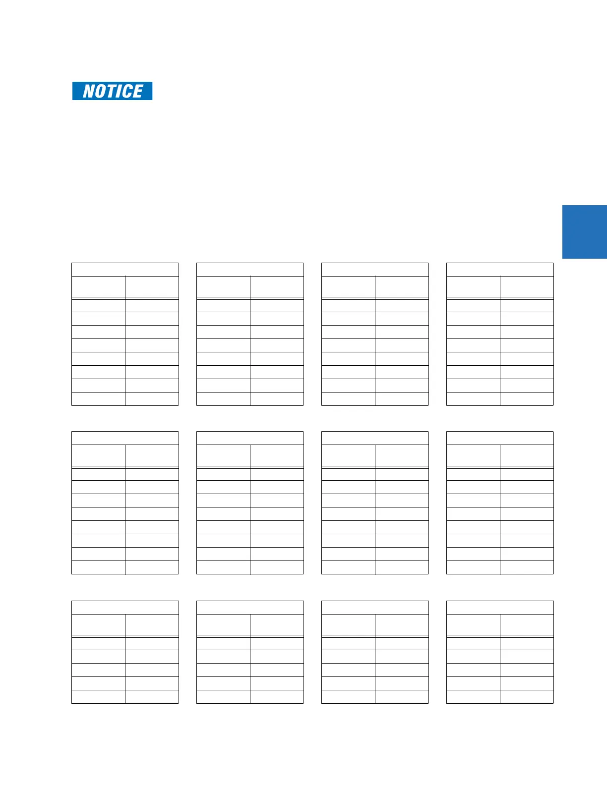
Table 3-3: Contact input and output module assignments
When current monitoring is used to seal-in the form-A and solid-state relay contact outputs, give the
FlexLogic operand driving the contact output a reset delay of 10 ms to prevent damage of the output
contact (in situations when the element initiating the contact output is bouncing, at values in the
region of the pickup value).
~6A module ~6B module ~6C module ~6D module
Terminal
assignment
Output or
input
Terminal
assignment
Output or
input
Terminal
assignment
Output Terminal
assignment
Output
~1 Form-A ~1 Form-A ~1 Form-C ~1a, ~1c 2 Inputs
~2 Form-A ~2 Form-A ~2 Form-C ~2a, ~2c 2 Inputs
~3 Form-C ~3 Form-C ~3 Form-C ~3a, ~3c 2 Inputs
~4 Form-C ~4 Form-C ~4 Form-C ~4a, ~4c 2 Inputs
~5a, ~5c 2 Inputs ~5 Form-C ~5 Form-C ~5a, ~5c 2 Inputs
~6a, ~6c 2 Inputs ~6 Form-C ~6 Form-C ~6a, ~6c 2 Inputs
~7a, ~7c 2 Inputs ~7a, ~7c 2 Inputs ~7 Form-C ~7a, ~7c 2 Inputs
~8a, ~8c 2 Inputs ~8a, ~8c 2 Inputs ~8 Form-C ~8a, ~8c 2 Inputs
~6E module ~6F module ~6G module ~6H module
Terminal
assignment
Output or
input
Terminal
assignment
Output Terminal
assignment
Output or
input
Terminal
assignment
Output or
input
~1Form-C~1Fast Form-C~1 Form-A ~1 Form-A
~2Form-C~2Fast Form-C~2 Form-A ~2 Form-A
~3Form-C~3Fast Form-C~3 Form-A ~3 Form-A
~4Form-C~4Fast Form-C~4 Form-A ~4 Form-A
~5a, ~5c 2 Inputs ~5Fast Form-C~5a,
~5c 2 Inputs ~5 Form-A
~6a, ~6c 2 Inputs ~6Fast Form-C~6a, ~6c 2 Inputs ~6 Form-A
~7a, ~7c 2 Inputs ~7Fast Form-C~7a, ~7c 2 Inputs ~7a, ~7c 2 Inputs
~8a, ~8c 2 Inputs ~8Fast Form-C~8a, ~8c 2 Inputs ~8a, ~8c 2 Inputs
~6K module ~6L module ~6M module ~6N module
Terminal
assignment
Output Terminal
assignment
Output or
input
Terminal
assignment
Output or
input
Terminal
assignment
Output or
input
~1 Form-C ~1Form-A~1Form-A~1Form-A
~2 Form-C ~2Form-A~2Form-A~2Form-A
~3 Form-C ~3Form-C~3Form-C~3Form-A
~4 Form-C ~4Form-C~4Form-C~4Form-A
~5 Fast Form-C ~5a, ~5c 2 Inputs ~5Form-C~5a, ~5c 2 Inputs