Revision C 250cx Series Maternal/Fetal Monitor 2-13
2036947-001
Equipment Overview: Rear Panel Description
CAUTION
NON-DESTRUCTIVE VOLTAGE—The maximum non-
destructive voltage that may be applied to the rear panel
connectors is 0 volts. Do not attempt to connect cables to these
connectors without contacting your Biomedical Engineering
Department or GE Medical Systems Information Technologies
Service Representative. This is to ensure the connectors comply
with leakage-current requirements of one of the following
applicable standards: Underwriters Laboratories UL-2601-1,
F
J112 External VGA Connector
Connector for external VGA display. Use of recommended
GE external display will allow monitor front panel display
video to be replicated remotely.
G
Speaker
The rear panel speaker emits an audible tone for heart rates,
MSpO
2
pulse with %O
2
-dependent pitch, and alarms. It also
provides the sound for the song player feature.
H
J109, J110, and J111 RS-232C
Communications Connectors
Three serial RJ-11 connectors are provided for interfacing
to peripheral equipment. Contact your GE Service
Representative for more information.
I
ECG Out Connector External recorder connector for MECG signals. The
standard output level is 1 V/mV.
J
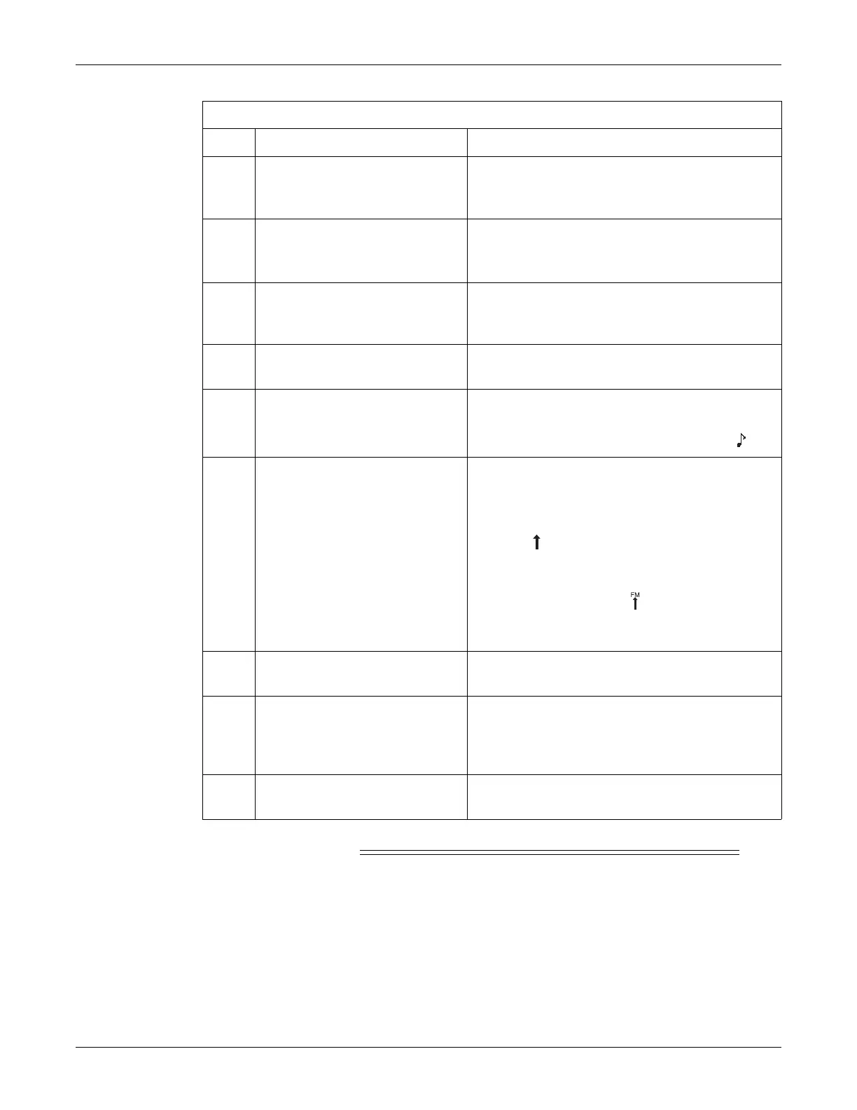
Fetal Acoustic Stimulator Connector Connector for Corometrics Model 146 Fetal Acoustic
Stimulator (FAST). A musical note symbol prints on the
strip chart paper each time the Model 146 is used:
K
Remote Event Marker Connector Connector for the Corometrics Remote Event Marker.
When activated, one of the following marks prints on the
strip chart paper:
The event marker is commonly used to record an
“event”:
The fetal movement marker (default setting) is
commonly used as an indication that the mother has
perceived fetal movement:
Refer to the “Coro 250cx Series Monitor Service Manual”
for more information.
L
Equipotential Lug A binding post terminal is directly connected to the chassis
for use as an equipotentiality connection.
M
AC Voltage Selection Switch This switch is intended for qualified service personnel to
select a voltage range for the AC input:
120: Accepts an AC input in the range of 100–120 VAC.
240: Accepts an AC input in the range of 220–240 VAC
N
Power Entry Module
AC line power cord connector. Refer to the rear panel markings
to verify line voltage and line frequency requirements.
Table 5. 250cx Series Rear Panel (Standard and Optional Features)
Name Description

 Loading...


