4-48 250cx Series Maternal/Fetal Monitor Revision C
2036947-001
Maintenance: RS-232C Connector Loopback Test
RS-232C Connector Loopback Test
The Communications Setup screen includes a loopback test option for each of the
communications ports: J109, J110, and J111. Running the test requires inserting a
loopback test connector into each port being tested. (You can test more than one port
at a time.)
Making a Loopback Test Connector
Start with an RJ-11C connector and bridge pin 2 (RXD) and pin 5 (TXD) together.
The figure below shows the pinout of a communications port while you face the rear
panel of a 250cx Series Monitor. Table 12 lists the signal description for each pin.
Testing the Port(s)
1. Access the
Communications Setup
screen (See
“Communications Screen”
on
page 4-49).
2. Insert a loopback test connector into each communications port being tested.
3. Set the mode field on the Communications Setup screen to Loopback. Notice that
the word Off displays to the right of the mode.
HR2 J102, pin 22
– – – –1.2 V ± 10 mV R27
240 bpm +1.2 V ± 10 mV R29
UA J102, pin 2
0 relative units
(mmHg and kPa)
–1.2 V ± 10 mV R42
100 mmHg
13.3 kPa
+1.2 V ± 10 mV R44
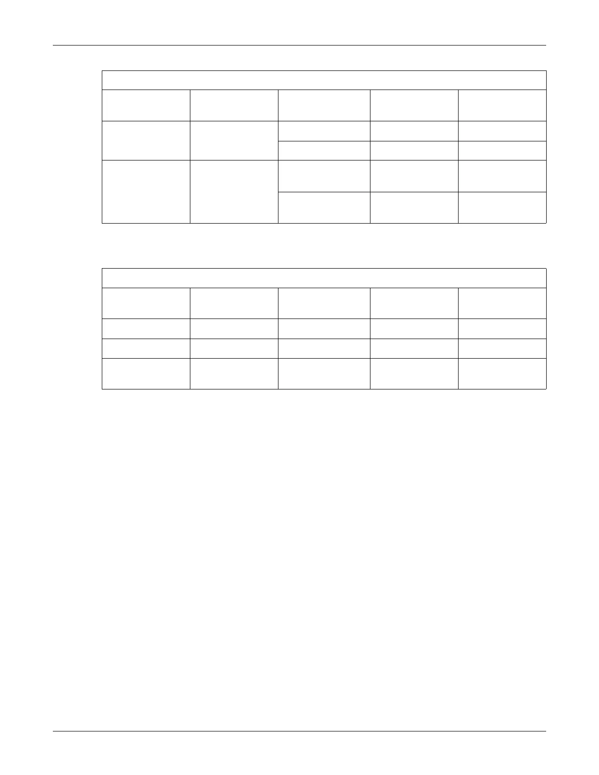
Table 10. DAC Output Voltages and Adjustment Points for Corometrics Central Station Outputs
Analog Signal Measurement Site
Service Screen
Setting
Expected Voltage Adjustment Site
Table 11. DAC Output Voltages and Adjustment Points for Hewlett-Packard Central Station Outputs
Analog Signal Measurement Site
Service Screen
Setting
Expected Voltage Adjustment Site
HR1 J102, pin 7 240 bpm +2.4V ± 10 mV R20
HR2 J102, pin 22 240 bpm +2.4 V ± 10 mV R29
UA J102, pin 2 100 mmHg
13.3 kPa
+10.0 V ± 24 mV R44

 Loading...


