Revision C 250cx Series Maternal/Fetal Monitor 4-47
2036947-001
Maintenance: J102 Analog Output Connector DAC Static Test
UA Mode
Use the Trim Knob control to select: – – –, INOP, Off, IUP, or TOCO.
Markout*, Check Paper*, FMD1, and FMD2
Use the Trim Knob control to alternate between On and Off.
NOTE: Signal names followed by an asterisk (*) or slash (/) are active low.
Calibration
For calibration, you must use the specific values listed in Table 10 (Corometrics
output levels) or Table 11 (Hewlett-Packard output levels). This tests the high and
low ranges for the HR1, HR2, and UA signals. If a measured value does not fall
within the given range, adjust the corresponding potentiometer accordingly (on
Communications Board, No. 13388 or 15297).
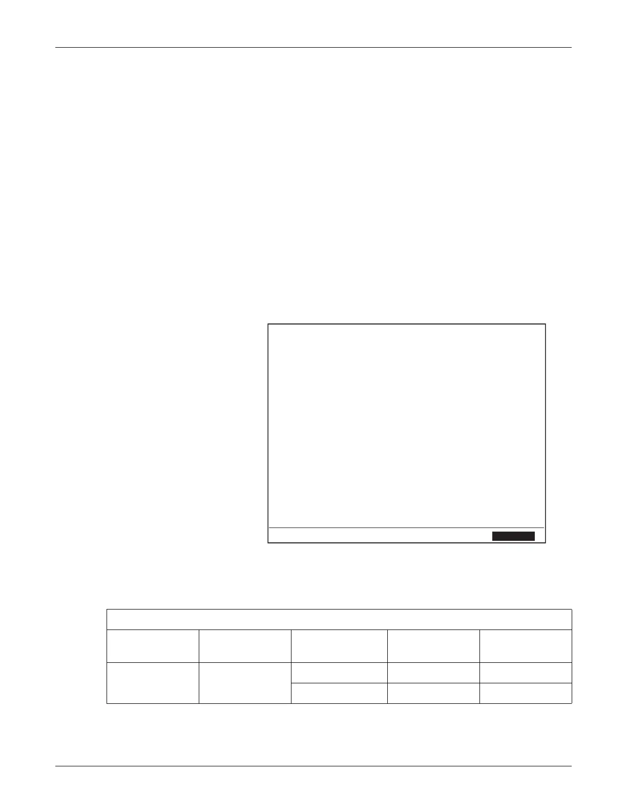
J102 Analog Output Connector Screen
J102
Pin Signal Range Voltage Meaning
3 Analog Gnd 0.00 0.0
7 HR1 ±1.2 -1.20 - - - bpm
22 HR2 ±1.2 -1.20 - - - bpm
2UA ±1.2 -1.20 0
17 HR1Mode ±10 -10.00
1 HR2Mode ±10 -10.00 Test
24 UAMode ±10 -10.00
20 Markout* 0-5 5 Off
18 Chk Paper* 0-5 5 Off
14 FMD1 0-5 0 Off
15 FMD2 0-5 0 Off
Decimal
Exit
Table 10. DAC Output Voltages and Adjustment Points for Corometrics Central Station Outputs
Analog Signal Measurement Site
Service Screen
Setting
Expected Voltage Adjustment Site
HR1 J102, pin 7
– – – –1.2 V ± 10 mV R18
240 bpm +1.2 V ± 10 mV R20

 Loading...


