2-22 250cx Series Maternal/Fetal Monitor Revision C
2036947-001
Equipment Overview: Theory of Operation
Main Board PWA
The Main Board makes up the central processing unit for the 250cx Series Fetal
Monitor. The Main Board accepts simultaneously processed parameters directly
from four separate modules. The minimum configuration monitor has only the DSP
board as an input module. Heart rate (ultrasound and or FECG), uterine activity data,
mode information, and FMD data, flow from the DSP board to the Main Board via
DSP board FPGA shared memory. Maternal and fetal Oximetry makes up the
second and third modules. Information from these devices is passed to the Main
Board via RS-232 ports. The Main Board communicates with the front panel UI
keypad PWA using RS-232 interface, which is routed through the DSP board. The
Main Board PWA also provides a master reset for the UI keypad PWA. The Main
Board holds the NIBP control circuitry (minus pump and valves) and communicates
to it using a CMOS interface. The Main Board PWA connects to the Pneumatics
PWA which holds the NIBP pump, valves, and filter. The Main PWA contains three
external RS232 data ports for various external devices and setup/code update
functions. The Main Board PWA receives data from the rear panel options PWA to
allow the added Communication features. The Main board PWA formats all the data
and interfaces to the recorder PWA. The Main PWA also controls all of the audio
functions including generated tones to passing ultrasound audio from the ultrasound
PWA. The following sections show the block diagram of the 250cx Series Main
Board PWA and the data flow between the modules the Main Board.
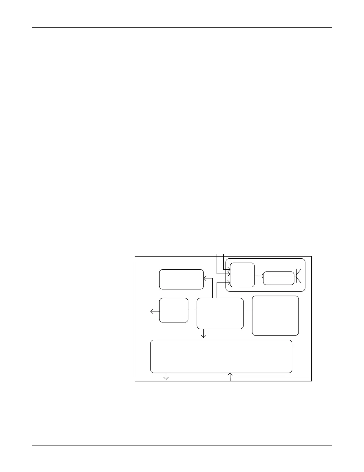
Main Board Block Diagram
Following diagram shows the Main Board block diagram with internal and external
interfaces.
MSpO
2
Connector PWA
The MSpO
2
Connector PWA receives the GEHC-IT universal SpO
2
patient cables
on the front bezel of the 250cx Series monitor and transfers the analog signals on to
MAIN
CONTROL BLOCK
1. 68302 up
2. rom+ram
3. adrs dec, clock module, RTC
4. Control /status module
AUDIO MUX
+
D/A VOLUME
CONTROLS
AUDIO AMPLIFIER
RECORDER
INTERFACE
1. data interface
2. motor interface
3. switch interface
Module
Recorder
To
DSP/front panel interface
1. 1k shared memory
2. Int input
3. reset output
OPTIONS INTERFACE
1. Rs232 Uart for ext SA02
2. RS232 Uart for ext NIBP
3. RS232 Uart for ext fsao2
COMMUNCATION MODULE
REAR PANEL IINTERFACE
US1
US2
ULTRASOUND BOARD
TO
AUDIO MODULE
+
MIXER
To DSP/front panel interface
1. fast, rem mark
2. FECG 80db,MECG 60db
5. Power-on reset module
4. Internal sao2 Uart
5. Internal Nibp Uart
1. J102 Interface
2. Keyboard Interface
4. Front panel Interface
Comm Bd int
To Comm Bd
6. Internal FSpO2 Uart

 Loading...


