EasyManuals Logo

GE LOGIQ P6 Service Manual

GE LOGIQ P6
478 pages
To Next Page IconTo Next Page
To Previous Page IconTo Previous Page
Page #242 background imageLoading...
Page #242 background image
GE HEALTHCARE
DIRECTION 5245279, REVISION 3 LOGIQ™ P6/P6 PRO SERVICE MANUAL
8 - 22 Section 8-2 - DISASSEMBLY/RE-ASSEMBLY
8-2-4-4 Assembly procedure (cont’d)
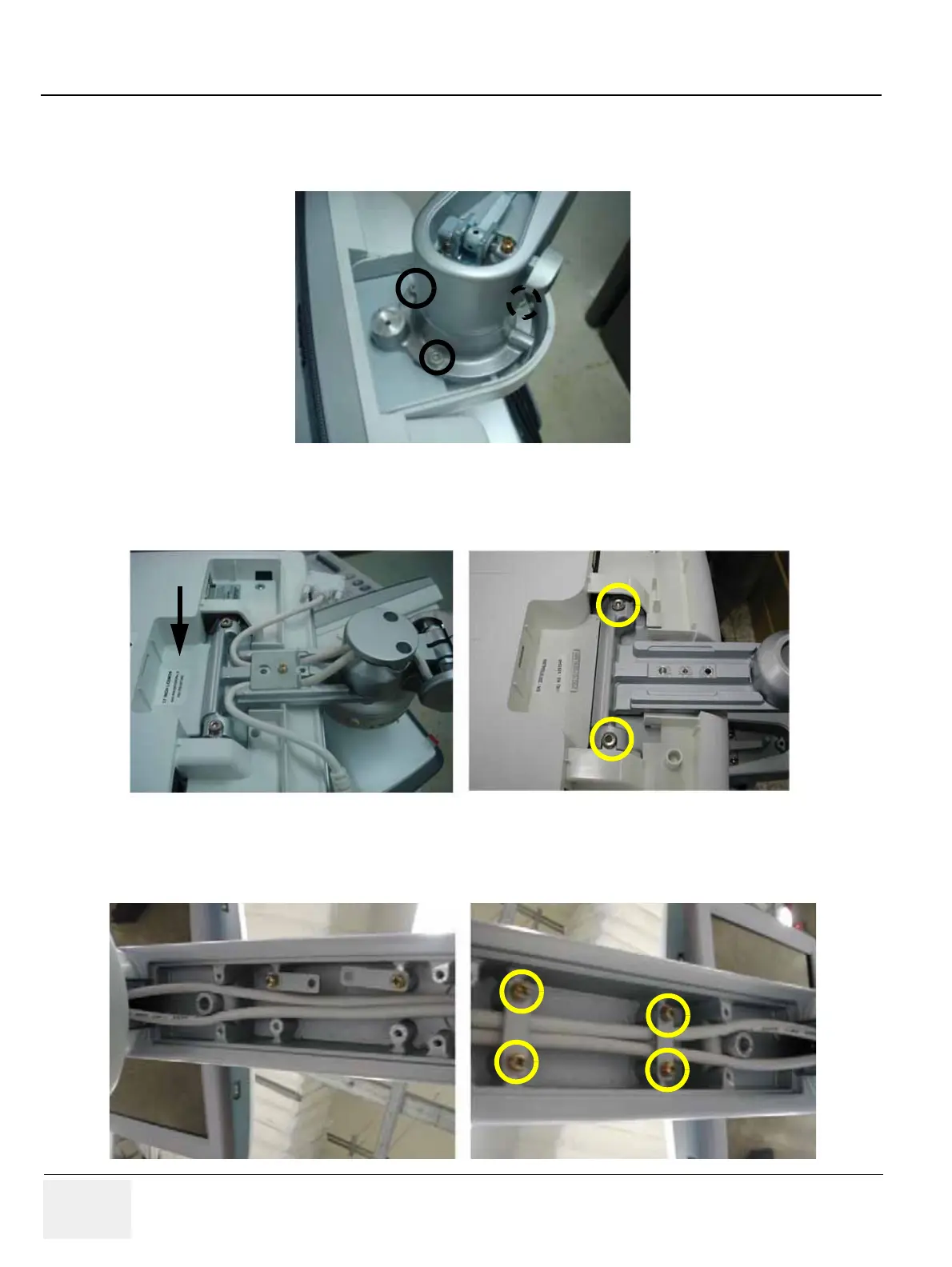
6.) Screw 3 screws (5327646, HSH M6 X 16 WHT) to install the arm neck pipe. Make sure place DVI
cable be on the right side, power cable on the left side. Refer to the figure below.
7.) Screw 2 screws (5177684, HSH M5X20 WHT) to assemble the LCD monitor with flexible arm Top
part. Refer to the figure below.
8.) Insert the two cables inside the Flexible arm and Screw 4 screws (2159625, PH M4X8 W/SP) to
assemble the Lower arm cable bracket.
Figure 8-41 Assembling the arm neck pipe
Figure 8-42 Screwing 2 screws
Figure 8-43 Screwing 4 screws

Table of Contents

Other manuals for GE LOGIQ P6

Questions and Answers:

Question and Answer IconNeed help?

Do you have a question about the GE LOGIQ P6 and is the answer not in the manual?

GE LOGIQ P6 Specifications

General IconGeneral
TypeUltrasound System
ConnectivityDICOM, USB, Ethernet
ApplicationsObstetrics, Gynecology, Vascular, Cardiology, Musculoskeletal
ProbesConvex, Linear, Phased Array
Imaging ModesB-mode, M-Mode, Color Doppler, Power Doppler, Pulsed Wave Doppler
PortabilityMobile
Transducer Ports3 active ports

Related product manuals