EasyManuals Logo

GE LOGIQ P6 Service Manual

GE LOGIQ P6
478 pages
To Next Page IconTo Next Page
To Previous Page IconTo Previous Page
Page #244 background imageLoading...
Page #244 background image
GE HEALTHCARE
DIRECTION 5245279, REVISION 3 LOGIQ™ P6/P6 PRO SERVICE MANUAL
8 - 24 Section 8-2 - DISASSEMBLY/RE-ASSEMBLY
8-2-4-4 Assembly procedure (cont’d)
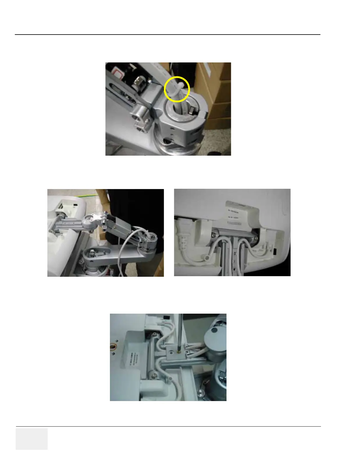
12.)Tie the Cables with Cable tie. Refer to the figure below.
13.)Place the cables inside the slot and connect power cable and DVI cable. Refer to the figure below.
14.)Assemble the cable bracket with 1 Screw (2159625, PH M4X8 W/SP).
Figure 8-47 Tying the cables
Figure 8-48 Placing the Cables
Figure 8-49 Assembling the Cable bracket

Table of Contents

Other manuals for GE LOGIQ P6

Questions and Answers:

Question and Answer IconNeed help?

Do you have a question about the GE LOGIQ P6 and is the answer not in the manual?

GE LOGIQ P6 Specifications

General IconGeneral
TypeUltrasound System
ConnectivityDICOM, USB, Ethernet
ApplicationsObstetrics, Gynecology, Vascular, Cardiology, Musculoskeletal
ProbesConvex, Linear, Phased Array
Imaging ModesB-mode, M-Mode, Color Doppler, Power Doppler, Pulsed Wave Doppler
PortabilityMobile
Transducer Ports3 active ports

Related product manuals