GE HEALTHCARE
DIRECTION 5245279, REVISION 3 LOGIQ™ P6/P6 PRO SERVICE MANUAL
Section 8-2 - DISASSEMBLY/RE-ASSEMBLY 8 - 37
8-2-6-3 Removal procedure (cont’d)
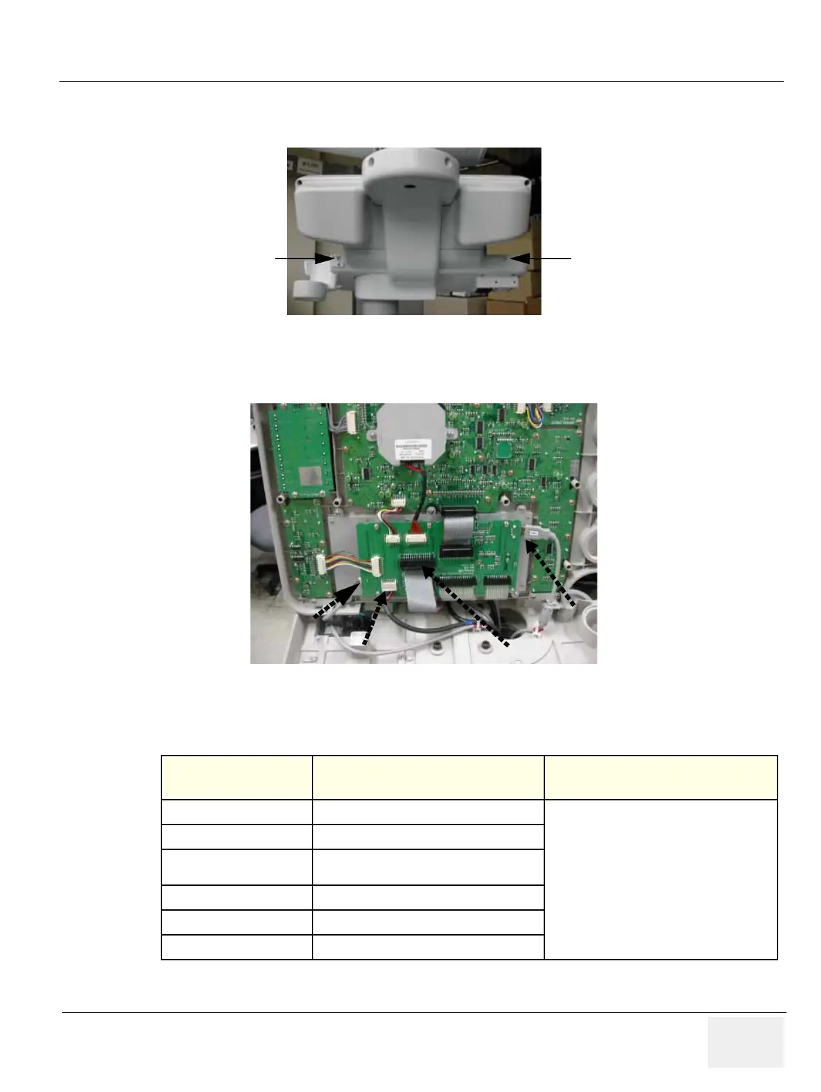
3.) Unscrew 2 screws from the rear side of the keyboard. Refer to the Figure 8-72.
4.) Lift the top cover of the keyboard and disconnect 4 cables from the keyboard. Refer to the Figure
8-73.
5.) Perform the following functional tests. If all are successful, include the debrief script provided below.
8-2-6-4 Mounting Procedure
Install the new parts in the reverse order of removal.
Figure 8-72 Unscrews 2 screws
Figure 8-73 Lifting the top cover & Disconnecting 5 Cables
Table 8-7 Functional Tests
Service Manual
Section
Functional Test / Diagnostic Test Debrief Script
Section 4-3-1
Power On/Boot Up
“Service Manual, Direction
5245279, Rev 3+, Section 8-2-6. Equipment
passed all required tests and is ready for use. “
Section 4-3-2
Power Off / Shutdown
Section 4-7-1
Main Keyboard Assy Function Validation
Procedure
Section 4-3-4
System B/M-Mode Checks
Section 4-3-5
System CFM and PWD Checks
Section 10-5-2
Functional Checks (See Also Chapter 4)
(1) (2)

 Loading...


