GE HEALTHCARE
DIRECTION 5245279, REVISION 3 LOGIQ™ P6/P6 PRO SERVICE MANUAL
8 - 98 Section 8-2 - DISASSEMBLY/RE-ASSEMBLY
8-2-45-3 Removal procedure (cont’d)
7.) Perform the following functional tests. If all are successful, include the debrief script provided below.
8-2-45-4 Mounting Procedure
Install the new parts in the reverse order of removal.
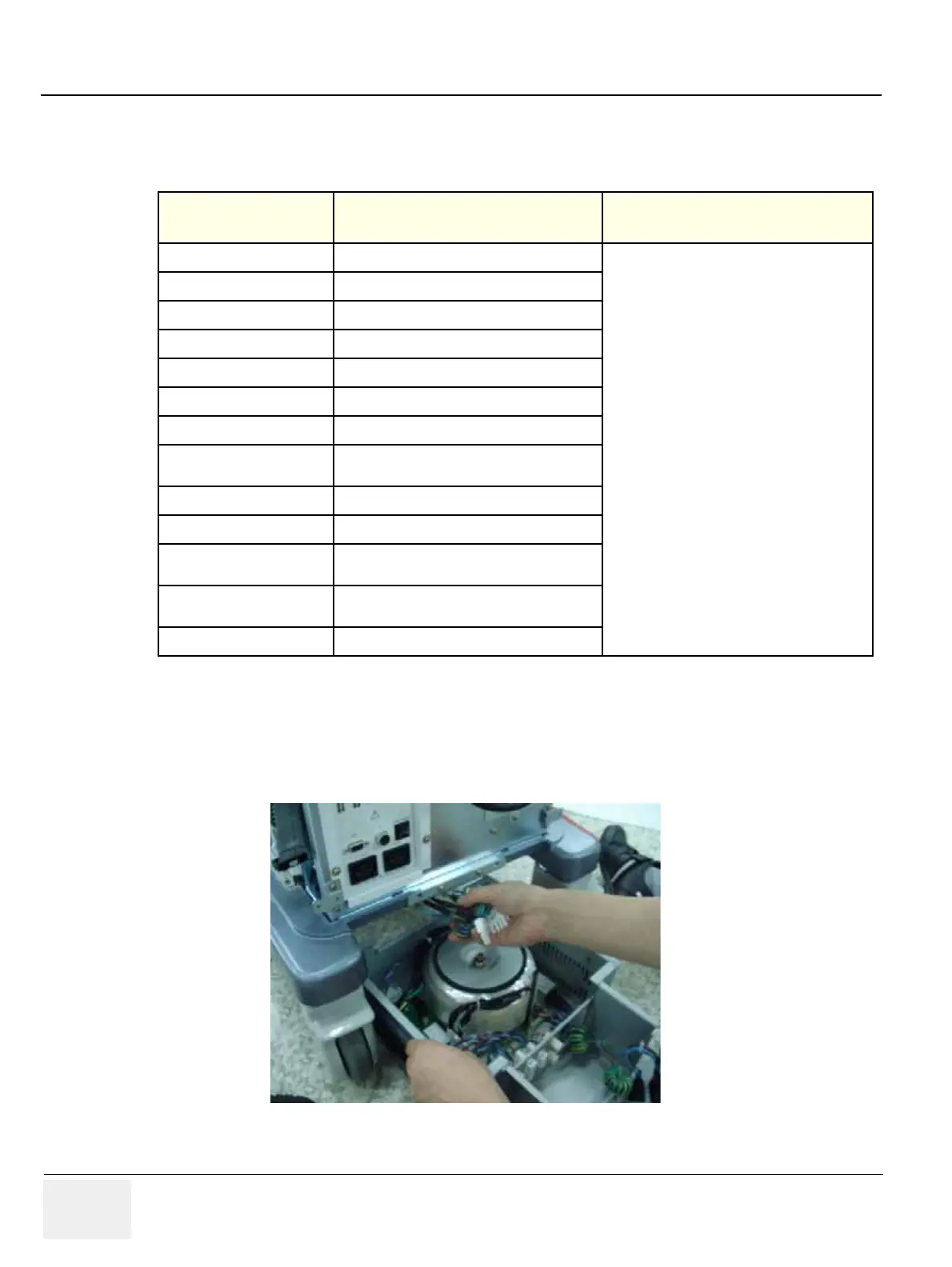
When install Transbox assy, the transbox chassie should be inserted into the guide rails which are under
the frame chassi.
Table 8-46 Functional Tests
Service Manual
Section Functional Test / Diagnostic Test Debrief Script
Section 4-3-1
Power On/Boot Up
“Service Manual, Direction
5245279, Rev 3+, Section 8-2-45. Equipment
passed all required tests and is ready for use. “
Section 4-3-2
Power Off / Shutdown
Section 4-9-10
Transbox/ Fan Function Validation Procedure
Section 10-5-2-2
Peripheral/Option Checks
Section 10-5-3
Input Power
Section 10-5-5
Probe Maintenance
Section 10-6-2
GEMS Leakage Current Limits
Section 10-6-3
Outlet Test - Wiring Arrangement - USA &
Canada
Section 10-6-4
Grounding Continuity
Section 10-6-5
Chassis Leakage Current Test
Section 10-6-6
Isolated Patient Lead (Source) Leakage–Lead
to Ground
Section 10-6-7
Isolated Patient Lead (Source) Leakage–Lead
to Lead
Section 10-6-9
Probe Leakage Current Test
Figure 8-145 Insert the Transbox assy

 Loading...


