GE HEALTHCARE
DIRECTION 5245279, REVISION 3 LOGIQ™ P6/P6 PRO SERVICE MANUAL
8 - 96 Section 8-2 - DISASSEMBLY/RE-ASSEMBLY
8-2-45 AP950 Assy
8-2-45-1 Tools
• Common philips screwdrivers
• Allen/Unbraco wrench
8-2-45-2 Preparations
• Shut down the system and switch off the main breaker.
8-2-45-3 Removal procedure
- To detache the AC Power assy, All open 4 pcs console cover that are left, right, front, rear
cover.
1.) Remove side left cover and right side cover. Refer to the 8-2-14 "Right or Left Side Cover" on page
8-47 and 8-2-14 "Right or Left Side Cover" on page 8-47.
2.) Remove rear side cover and front cover. Refet to the 8-2-15 "Front Cover" on page 8-49 and 8-2-
16 "Rear Cover" on page 8-51.
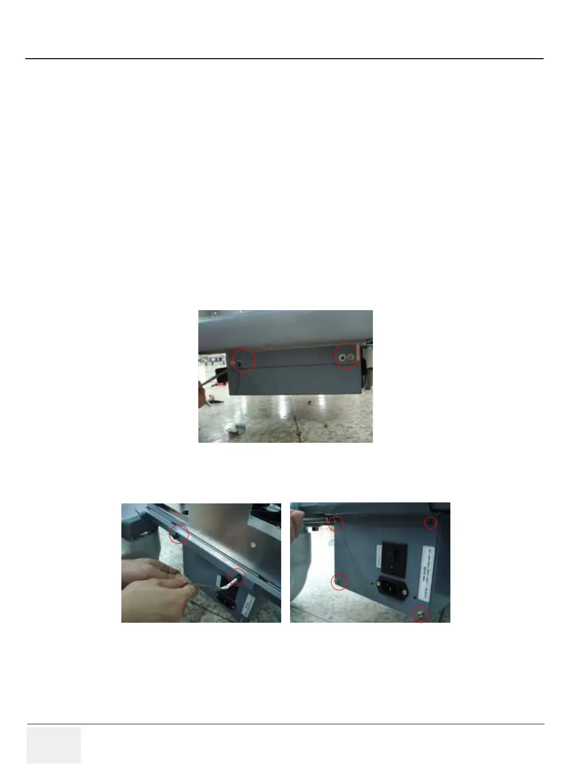
3.) Unscrew 2 M4 screws and 2 Hexa screws on the front of AC trans box.Refer to the Figure 8-141.
4.) Loosen 2 Hex (left side in Figure 8-144)screws and 4 M4 screws (right side of Figure 8-142).
Figure 8-141 4 screw on the front of the AC TRANSBOX
Figure 8-142 Back of the AC TRANSBOX

 Loading...


