GE HEALTHCARE
DIRECTION 5245279, REVISION 3 LOGIQ™ P6/P6 PRO SERVICE MANUAL
Section 8-2 - DISASSEMBLY/RE-ASSEMBLY 8 - 99
8-2-46 Fuse Set
8-2-46-1 Tools
• Common philips screwdrivers
• Allen/Unbraco wrench
• Stubby screwdriver (Flat tip and Cross tip)
8-2-46-2 Preparations
• Shut down the system and switch off the main breaker.
8-2-46-3 Removal procedure
1.) Remove the AC Transbox assy. Refer to the 8-2-42 "ARP II Assy 110V/220V" on page 8-90.
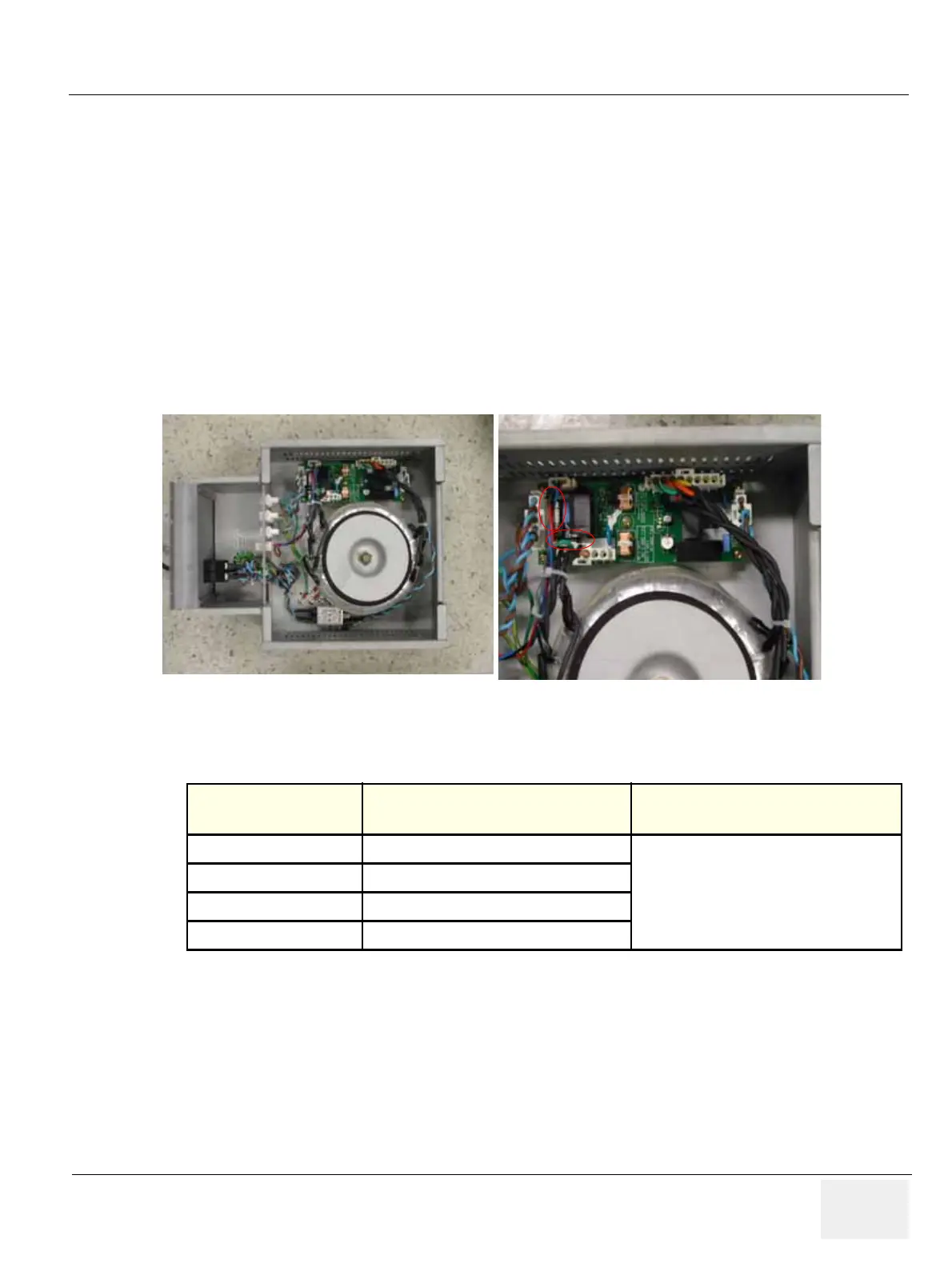
2.) Replace the 2 fuses located on the ACPC II assy in the transbox assy. Refer to the Figure 8-146.
3.) Perform the following functional tests. If all are successful, include the debrief script provided below.
8-2-46-4 Mounting Procedure
Install the new parts in the reverse order of removal.
Figure 8-146 FUSE in Transbox(AP950) assy
Table 8-47 Functional Tests
Service Manual
Section
Functional Test / Diagnostic Test Debrief Script
Section 4-3-1
Power On/Boot Up
“Service Manual, Direction
5245279, Rev 3+, Section 8-2-46. Equipment
passed all required tests and is ready for use. “
Section 4-3-2
Power Off / Shutdown
Section 4-9-14
Fuse set Function Validation Procedure
Section 10-5-2-2
Peripheral/Option Checks

 Loading...


