GE HEALTHCARE
DIRECTION 5245279, REVISION 3 LOGIQ™ P6/P6 PRO SERVICE MANUAL
8 - 166 Section 8-7 - Mechanical Option Installation instruction
8-7-1-4 Assembly procedure (cont’d)
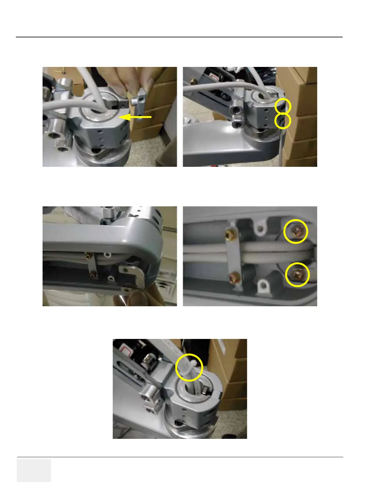
10.) Screw 2 screws (2159626, PH M4X20) to assemble the Arm stopper. Refer to the figure below.
11.) Screw 2 screws (2159625, PH M4X8 W/SP) to assemble the Lower arm guide bracket.Refer to the
figure below.
12.) Tie the Cables with Cable tie. Refer to the figure below.
Figure 8-259 Installing the Arm Stopper
Figure 8-260 Assembling the Lower arm guide Bracket
Figure 8-261 Tying the cables

 Loading...


