GE HEALTHCARE
DIRECTION 5245279, REVISION 3 LOGIQ™ P6/P6 PRO SERVICE MANUAL
Section 8-7 - Mechanical Option Installation instruction 8 - 171
8-7-1-4 Assembly procedure (cont’d)
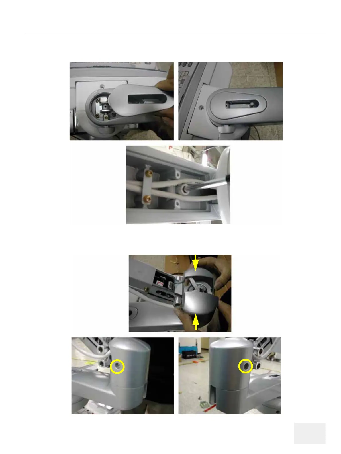
21.) Screw 1 screw (2329677, TAP M4X16) to assemble the Lock Cover.
22.) Screw 2 screws (2159632, BH M4X6 WHT) to assemble the Cam Cover L & R.
Figure 8-270 Assembling the Lock Cover
Figure 8-271 Assembling the Cam Cover L & R

 Loading...


