44x/EN AP/Hb6
-40 MiCOM P40 Agile
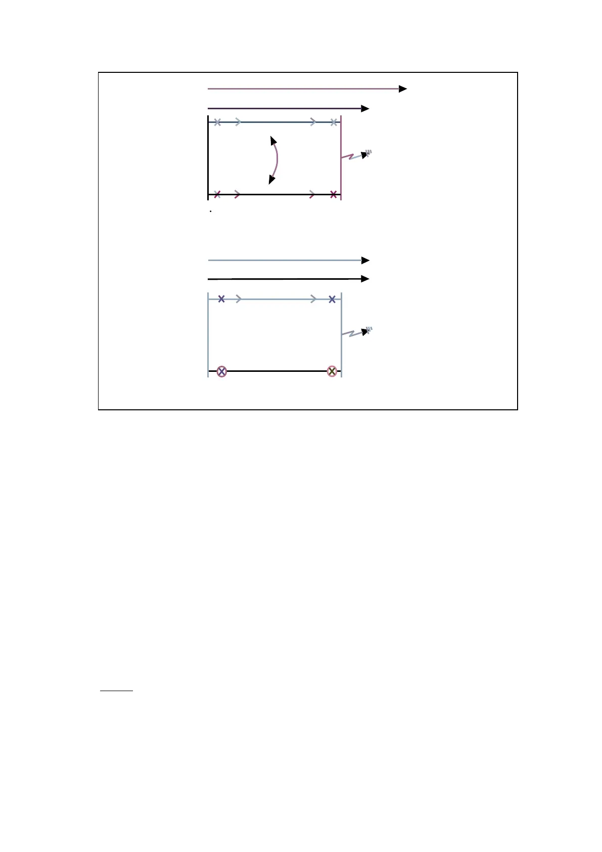
Z2 ' Boost ' G/F
Z2 ' Reduced ' G/F
(i) Group 1
(ii) Group 2
Z2 PH
Z2 PH
ZMO
P3049EN
Figure 19: Mutual Coupling example - zone 2 reach considerations
3.1.2.2 Zone setting – KZ Residual compensation for Earth Fault Elements and KZ Angle
The reaches of the earth fault elements use residual compensation of the corresponding
phase fault reach. The residual compensation factors are:
• kZ1 - For zone 1 and zone 1X;
• kZ2 - For zone 2;
• kZ3/4 - Shared by zones 3 and 4;
• kZp - For zone p;
• kZq - For zone q.
For earth faults, residual current either measured or derived as the vector sum of phase
current inputs (Ia + Ib + Ic) is assumed to flow in the residual path of the earth loop circuit.
Therefore, the earth loop reach of any zone must generally be extended by a multiplication
factor of (1 + kZ0) compared to the positive sequence reach for the corresponding phase
fault element. kZ0 is designated as the residual compensation factor, and is calculated as:
kZ0 Res. Comp, kZ0 = (Z
0
– Z
1
) / 3.Z
1
Set as a ratio.
kZ0 Angle, ∠kZ0 = ∠ (Z
0
– Z
1
) / 3.Z
1
Set in degrees.
Where:
Z
1
= Positive sequence impedance for the line or cable;
Z
0
= Zero sequence impedance for the line or cable.
kZ0 CALCULATION DESCRIPTION
If we consider a phase to earth fault AN with analogue values VA and IA.
Using symmetrical components, VA is described as follows:
(1) VA = V1 + V2 + V0 = Z1I1 + Z2I2 + Z0I0