Design
P44x/EN FD/Hb
P444 (FD) 8-
CT
CT
Buffer
16-bit
ADC
Sample
control
Serial
Interface
16:1
Multiplexer
Up to5current inputs
Serial sample
data bus
Parallel bus
Parallel bus
Trigger from
processor board
Anti-alias filters
Up to 5Up to 5 Up to 5
Diffn
to
single
Diffn
to
single
Low
pass
filter
Low
pass
filter
VT
VT
3/4 voltage inputs
Transformer board
Input board
44
Diffn
to
single
Diffn
to
single
Low
pass
filter
Low
pass
filter
Calibration
E²PROM
Optical
isolator
8 digital inputs
Noise
filter
Optical
isolator
P3027ENa
4
Buffer
Noise
filter
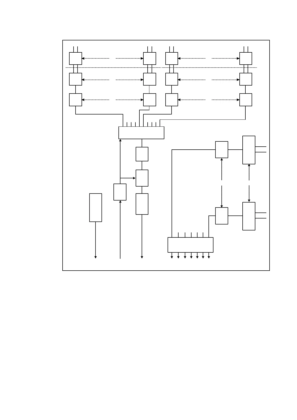
Figure 2 - Main Input Board
The other function of the input board is to read the state of the signals present on the digital
inputs and present this to the parallel data bus for processing. The input board holds 8
optical isolators for the connection of up to eight digital input signals. The opto-isolators are
used with the digital signals for the same reason as the transformers with the analogue
signals; to isolate the relay’s electronics from the power system environment. A 48 V ‘field
voltage’ supply is provided at the back of the relay for use in driving the digital opto-inputs.
The input board provides some hardware filtering of the digital signals to remove unwanted
noise before buffering the signals for reading on the parallel data bus. Depending on the
relay model, more than 8 digital input signals can be accepted by the relay. This is achieved
by the use of an additional opto-board which contains the same provision for 8 isolated
digital inputs as the main input board, but does not contain any of the circuits for analogue
signals which are provided on the main input board.
Each input also has selectable filtering which can be utilised.
The P440 series relays are fitted with universal opto isolated logic inputs that can be
programmed for the nominal battery voltage of the circuit of which they are a part i.e. thereby
allowing different voltages for different circuits e.g. signalling, tripping. In the ‘Opto Config’
menu, they can also be programmed as Standard “60% – 80%” or “50% – 70%” to satisfy
different operating constraints.
Threshold levels are as follows: