44x/EN MT/Hb6
-8 MiCOM P40 Agile P442,
P442
J H G F E D C B A
Relay Board (or
optional high break
Opto-
Opto-
Optional board
P444
N M L K J H G F E D C B A
Relay Board (or
optional high break
Relay Board (or
optional high break
(or
high break
Opto-
d
Opto-
Opto-
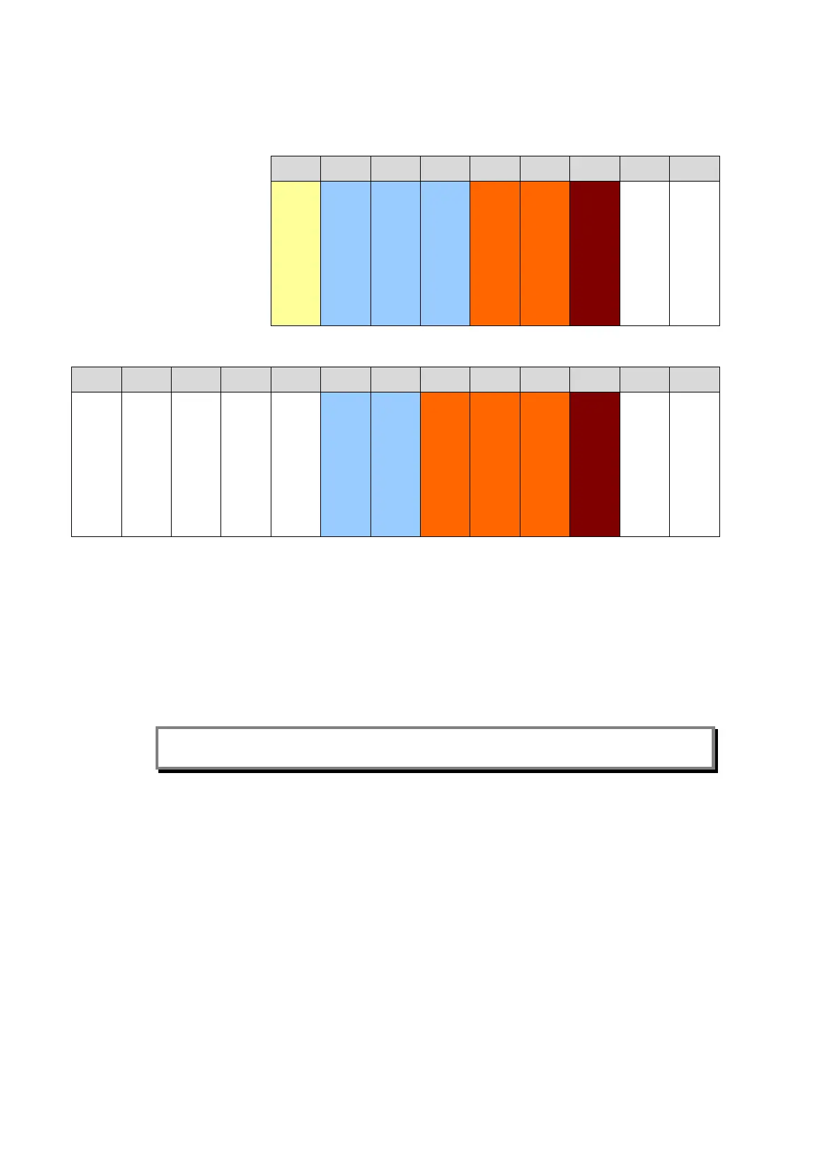
Figure 2 - P44x PCB/Module Locations (Viewed from front)
The PCBs within the relay are now accessible, Figure 2 show the PCB locations for the
distance relays in size 60TE (P442).
The 64-way ribbon cable to the front panel also provides the electrical connections between
PCBs with the connections being via IDC connectors.
The slots inside the case to hold the PCBs securely in place each correspond to a rear
terminal block. Looking from the front of the relay these terminal blocks are labelled from
right to left.
Note: To ensure compatibility, always replace a faulty PCB with one of an identical part
number. Table 1 lists the part numbers of each PCB type.