P44x/EN TS/Hb
P442, P444 (TS) 11-
3 POWER UP ERRORS
If the relay does not appear to power up then the following procedure can be used to
determine whether the fault is in the external wiring, auxiliary fuse, power supply module of
the relay or the relay front panel.
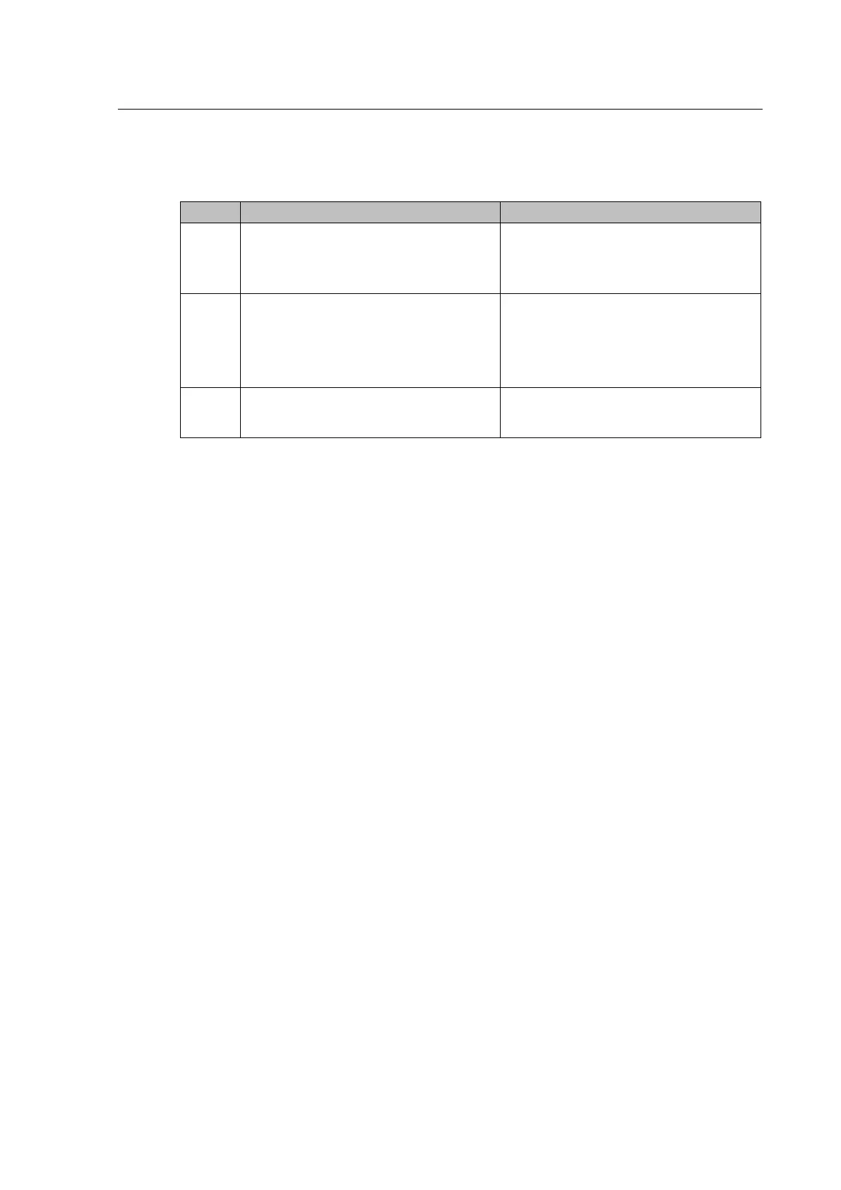
1
Measure auxiliary voltage on terminals 1
and 2; verify voltage level and polarity
against rating the label on front.
Terminal 1 is –dc, 2 is +dc
If auxiliary voltage is present and correct,
then proceed to test 2. Otherwise the
wiring/fuses in auxiliary supply should be
checked.
2
Do LEDs/and LCD backlight illuminate on
power-up, also check the N/O watchdog
contact for closing.
If they illuminate or the contact closes and
no error code is displayed then error is
probably in the main processor board
(front panel). If they do not illuminate and
the contact does not close then proceed to
test 3.
3
Check Field voltage output (nominally
48 V DC)
If field voltage is not present then the fault
is probably in the relay power supply
module.
Table 2: Failure of relay to power up
 Loading...


