P44x/EN IN/Hb
P442, P444 (IN) 14-
Further details on mounting MiDOS relays can be found in publication R7012, “MiDOS Parts
Catalogue and Assembly Instructions”.
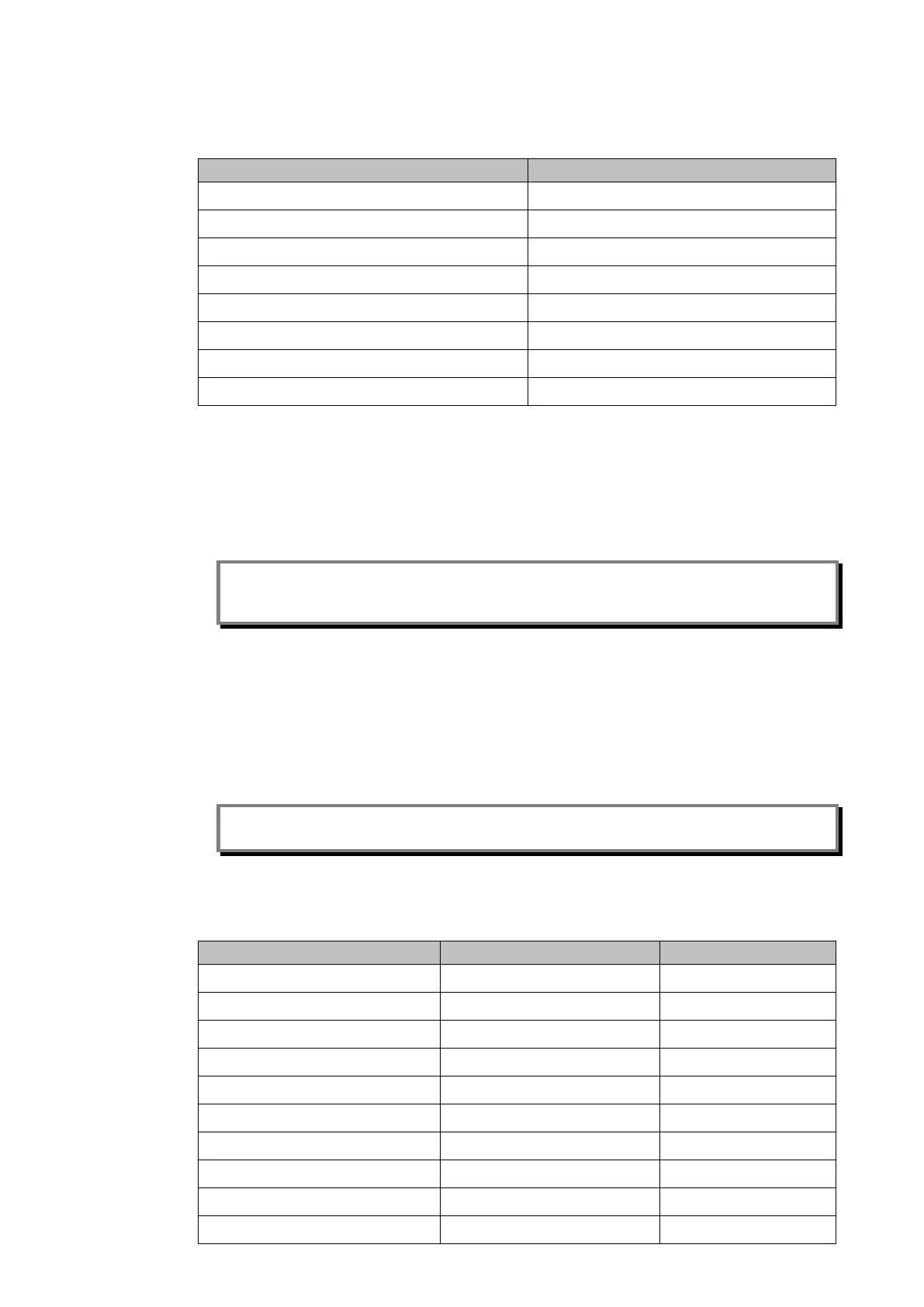
Blanking plate part number
5TE GJ2028 001
10TE GJ2028 002
15TE GJ2028 003
20TE GJ2028 004
25TE GJ2028 005
30TE GJ2028 006
35TE GJ2028 007
40TE GJ2028 008
Table 1 - Blanking plates
5.2 Panel mounting
The relays can be flush mounted into panels using M4 SEMS Taptite self-tapping screws
with captive 3mm thick washers (also known as a SEMS unit).
Note: Conventional self-tapping screws, including those supplied for mounting MIDOS
relays, have marginally larger heads which can damage the front cover moulding if
used.
Alternatively tapped holes can be used if the panel has a minimum thickness of 2.5mm.
For applications where relays need to be semi-projection or projection mounted, a range of
collars are available.
Where several relays are to mounted in a single cut-out in the panel, it is advised that they
are mechanically grouped together horizontally and/or vertically to form rigid assemblies
prior to mounting in the panel.
Note: It is not advised that MiCOM relays are fastened using pop rivets as this will not allow
the relay to be easily removed from the panel in the future if repair is necessary.
If it is required to mount a relay assembly on a panel complying to BS EN60529 IP52, it will
be necessary to fit a metallic sealing strip between adjoining relays (Part no GN2044 001)
and a sealing ring selected from Table 2 around the complete assembly.
10TE GJ9018 002 GJ9018 018
15TE GJ9018 003 GJ9018 019
20TE GJ9018 004 GJ9018 020
25TE GJ9018 005 GJ9018 021
30TE GJ9018 006 GJ9018 022
35TE GJ9018 007 GJ9018 023
40TE GJ9018 008 GJ9018 024
45TE GJ9018 009 GJ9018 025
50TE GJ9018 010 GJ9018 026
55TE GJ9018 011 GJ9018 027