b6
CM) 9-18
MiCOM P40 Agile P442, P444
[022F: IM Mutual Current Mag] or [0209:
0A0C:MComp CT Sec'y
Table 9 - CT Ratio Settings
4.2.11 Voltage Inputs
This test verifies that the accuracy of voltage measurement is within the acceptable
tolerances.
Apply rated voltage to each voltage transformer input in turn, checking its magnitude using a
multimeter. Refer to Table 8 for the corresponding reading in the relay’s
MEASUREMENTS 1 column and record the value displayed.
Cell in MEASUREMENTS 1 column (02) Voltage applied To
[021A: VAN Magnitude] C19-C22
[021C: VBN Magnitude] C20-C22
[021E: VCN Magnitude] C21-C22
[022B: C/S Voltage Mag]
∗
or [0222: VN Mag]
C23-C24
Table 10 - Voltage Input Terminals
The measured voltage values on the relay will either be in primary or secondary volts. If cell
[0D02: MEASURE’T SETUP, Local Values] is set to ‘Primary’, the values displayed on the
relay should be equal to the applied voltage multiplied by the corresponding voltage
transformer ratio set in the ‘VT and CT RATIOS’ menu column (see Table 11). If cell [0D02:
MEASURE’T SETUP, Local Values] is set to ‘Secondary’, the value displayed should be
equal to the applied voltage.
The measurement accuracy of the relay is ±2%. However, an additional allowance must be
made for the accuracy of the test equipment being used.
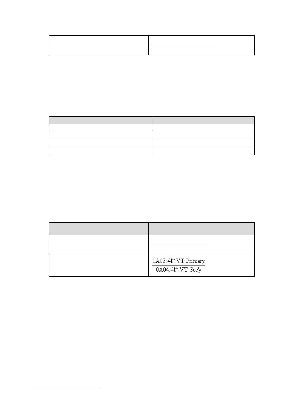
Cell in MEASUREMENTS 1 column (02)
Corresponding VT Ratio
(in ‘VT and CT RATIO column (0A) of menu)
[021A: VAN Magnitude]
[021C: VBN Magnitude]
[021E: VCN Magnitude]
0A01:Main VT Primary
0A02:Main VT Sec'y
[022B: C/S Voltage Mag] or [0223: VN Ang]
Table 11 - VT Ratio Settings
∗
Voltage reference for synchrocheck
Can be PGnd or PP reference with VT bus side or VT line
(see setting description in chapter AP section 4.4)