b6
CM) 9-20
MiCOM P40 Agile P442, P444
5.3 Demonstrate Correct Distance Function Operation
5.3.1 Functional Tests: Start control & Distance characteristic limits
Despite of working in 100% numerical technology some tests could be performed in order to
check that the relay has the right characteristics; regarding the different choices for functions
and settings (protection (with MiCOM S1 Agile / settings & records) and logic schemes (with
MiCOM S1 Agile / PSL Editor) settings).
Subsection 5.3.2 explains point by point the steps to follow to perform a complete check of
every distance protection functions of the relay (with the factory’s settings & PSL: "P&C by
default").
In the event of relay or application’s failure:
WARNING: RETURN TO THE BASIC CONFIGURATION (SETTINGS & PSL)
AND THEN VALIDATE THE TESTS FOLLOWING THE ENCLOSED
DESCRIPTION (VIA THE LCD ON THE FRONT PANEL
(CONFIGURATION/RESTORE DEFAULTS/ALL SETTINGS+VALIDATE))
The default password possibly required to confirm the settings is:
AAAA
Note: Every action performed using a laptop could also be performed using the LCD front
panel (only PSL and Text Editor require a computer)
5.3.1.1 Measurements check:
Before starting the tests, perform the following injections on the secondary side of the relay:
IA 0.2 In 0°
Currents IB 0.4 In - 120°
TEST 1
IC 0.8 In + 120°
VAN 30 V 0°
Voltages VBN 40 V - 120°
VCN 50 V + 120°
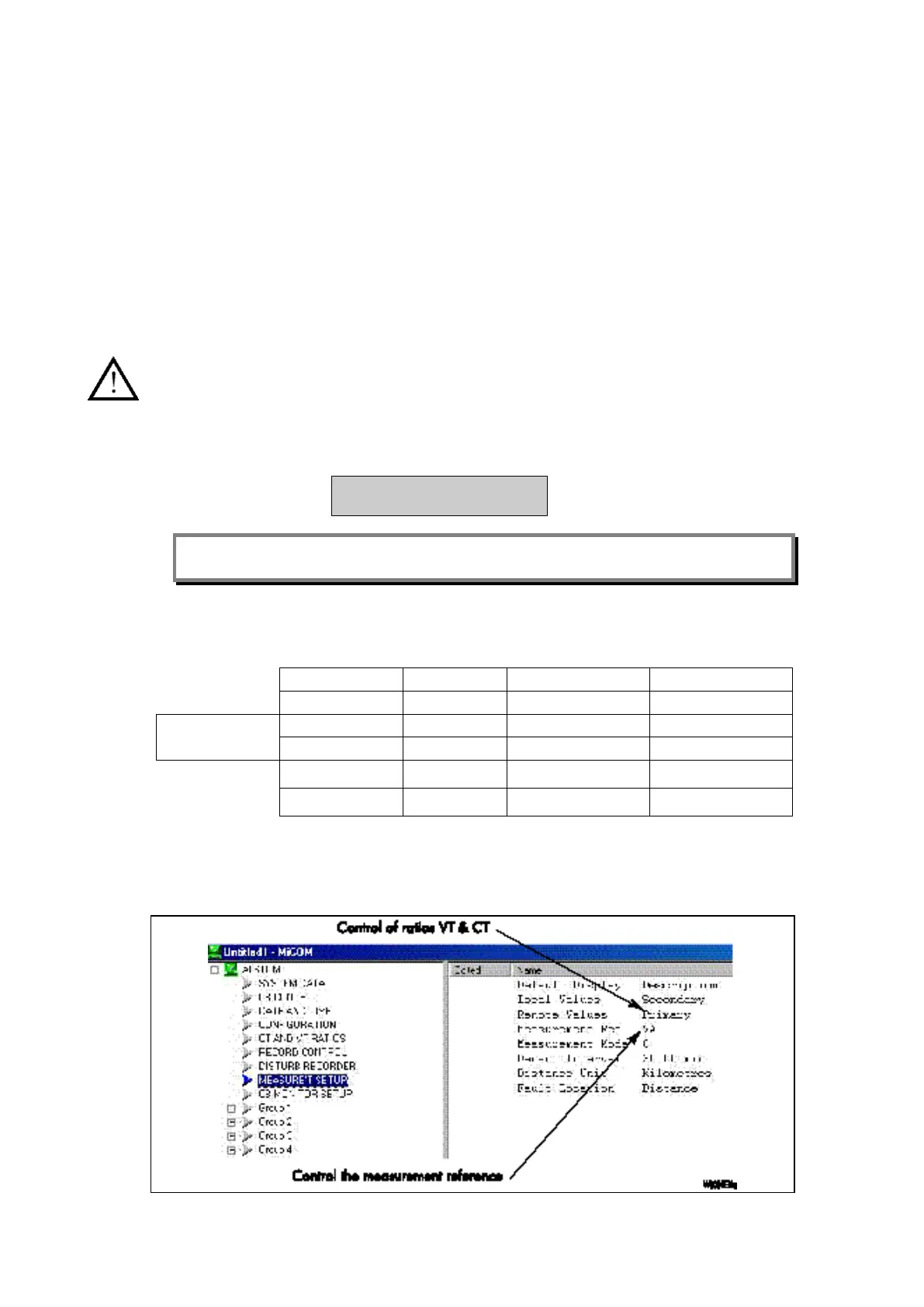
• Check the displayed values on the relay’s front panel (LCD):"system/meas1"
• Secondary values in amplitude and phase
• Or primary values (control of ratios VT & CT) – If selected:
Figure 2: