b6
CM) 9-14
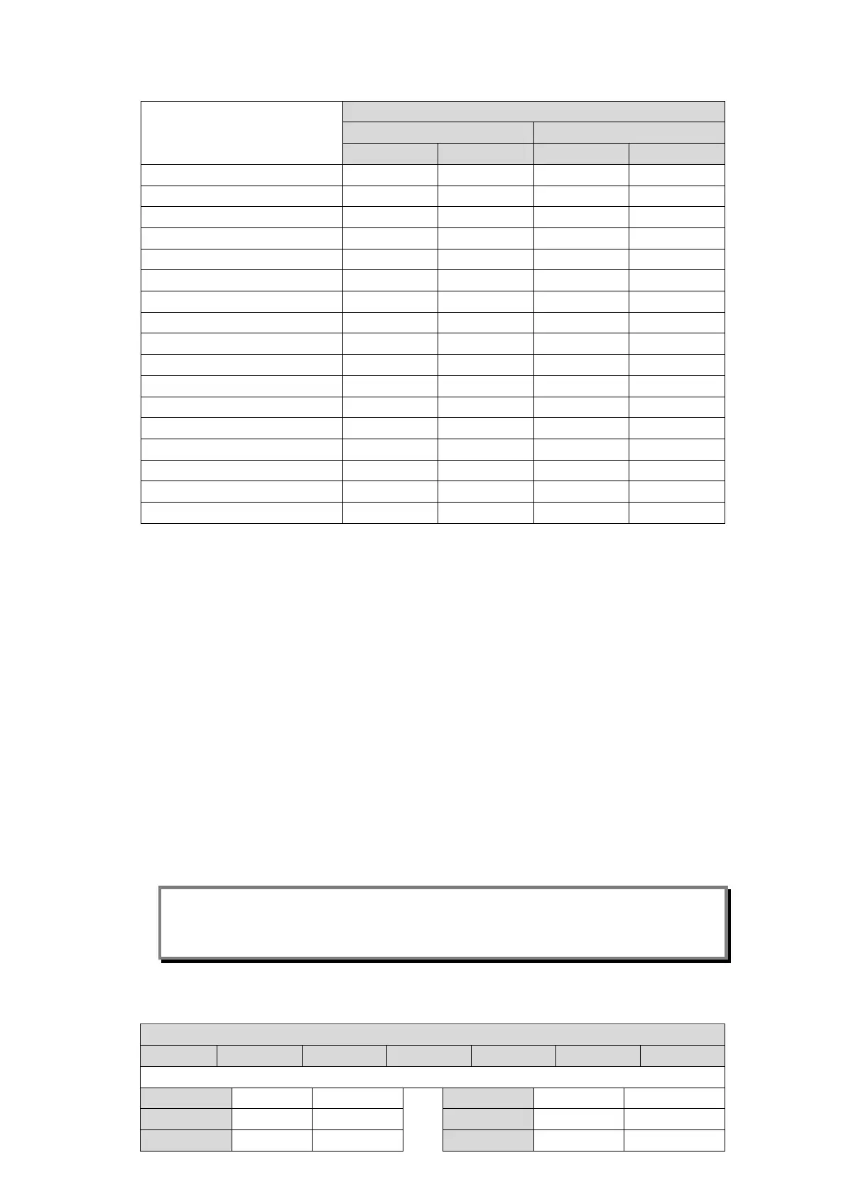
MiCOM P40 Agile P442, P444
Apply field voltage to terminals
-ve +ve -ve +ve
Opto input 8 D15 D16 D15 D16
Opto input 9 E1 E2 E1 E2
Opto input 10 E3 E4 E3 E4
Opto input 11 E5 E6 E5 E6
Opto input 12 E7 E8 E7 E8
Opto input 13 E9 E10 E9 E10
Opto input 14 E11 E12 E11 E12
Opto input 15 E13 E14 E13 E14
Opto input 16 E15 E16 E15 E16
Opto input 17 F1 F2
Opto input 18 F3 F4
Opto input 19 F5 F6
Opto input 20 F7 F8
Opto input 21 F9 F10
Opto input 22 F11 F12
Opto input 23 F13 F14
Opto input 24 F15 F16
Table 5 - Opto-isolated Input Terminals
4.2.8 Output Relays
This test checks that all the output relays are functioning correctly. The P442 relays have 21
output relays and the P444 relays have 32 output relays.
Ensure that the relay is still in test mode by viewing cell [0F0E: COMMISSIONING TESTS,
Test Mode].
The output relays should be energised one at a time. To select output relay 1 for testing, set
cell [0F0F: COMMISSIONING TESTS, Test Pattern] as shown in Table 6.
Connect a continuity tester across the terminals corresponding to output relay 1 given in
Table 6.
To operate the output relay set cell [0F11: COMMISSIONING TESTS, Contact Test] to
‘Apply Test’. Operation will be confirmed by the continuity tester operating for a normally
open contact and ceasing to operate for a normally closed contact.
Reset the output relay by setting cell [0F11: COMMISSIONING TESTS, Contact Test] to
‘Remove Test’.
Note: Ensure that thermal ratings of anything connected to the output relays during the
contact test procedure are not exceeded by the associated output relay being
operated for too long. It is therefore advised that the time between application and
removal of contact test be kept to the minimum.
Repeat the test for all the other output relays (number depends on the model).
MiCOM P442
Output N/C N/O Output N/C N/O
Without high break relay board (all models except P442×××C)
Relay 1 - H1-H2 Relay 12 G10-G12 G11-G12
Relay 2 - H3-H4 Relay 13 G13-G15 G14-G15
Relay 3 - H5-H6 Relay 14 G16-G18 G17-G18