44x/EN AP/Hb6
-72 MiCOM P40 Agile
T
iger Bay
System Data
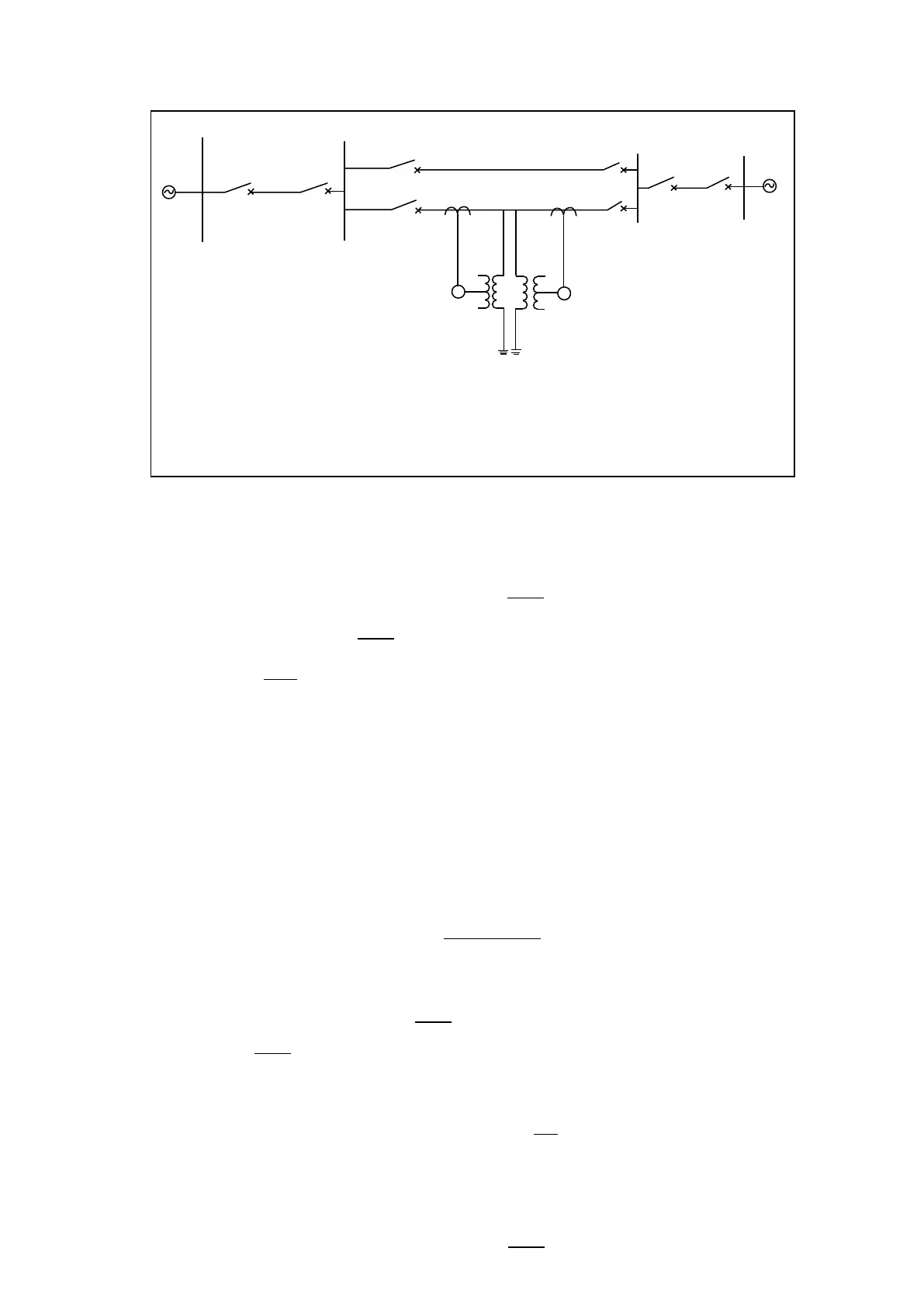
Green Valley - Blue River transmission line
System voltage 230kv
System grounding solid
CT ratio 1200/5
VT ratio 230000/115
Line length 100km
Line impedance
Z1 = 0.089 + J0.476 OHM/km
Z0 = 0.426 + J1.576 OHM/km
Faults levels
Green Valley substation busbars maximum 5000MVA, minimum 2000MVA
Blue River substation busbars maximum 3000MVA, minimum 1000MVA
80 Km
Green valley
P3074EN
100 Km
Blue River
Rocky bay
60 Km
21
21
Figure 49: System assumed for worked example
3.4.1.2 System Data
Line length: 100km
Line impedances: Z
1
= 0.089 + j0.476 = 0.484 / 79.4° Ω/km
Z
0
= 0.426 + j1.576 = 1.632 / 74.8° Ω/km
Z
0
/Z
1
= 3.372 / -4.6°
CT ratio: 1 200 / 5
VT ratio: 230 000 / 115
3.4.1.3 Relay Settings
It is assumed that Zone 1 Extension is not used and that only three forward zones are
required. Settings on the relay can be performed in primary or secondary quantities and
impedances can be expressed as either polar or rectangular quantities (menu selectable).
For the purposes of this example, secondary quantities are used.
3.4.1.4 Line Impedance
Ratio of secondary to primary impedance
= 0.12
Line impedance secondary = ratio CT/VT x line impedance primary.
Line Impedance = 100 x 0.484 / 79.4° (primary) x 0.12
= 5.81 / 79.4° Ω secondary.
Relay Line Angle settings -90° to 90° in 1° steps. Therefore, select Line Angle = 80° for
convenience.
Therefore set Line Impedance and Line Angle: = 5.81 / 80° Ω secondary.
3.4.1.5 Zone 1 Phase Reach Settings
Required Zone 1 reach is to be 80% of the line impedance between Green Valley and Blue
River substations.
Required Zone 1 reach = 0.8 x 100 x 0.484 / 79.4° x 0.12
 Loading...


