44x/EN PL/Hb6
-56 MiCOM 40 Agile
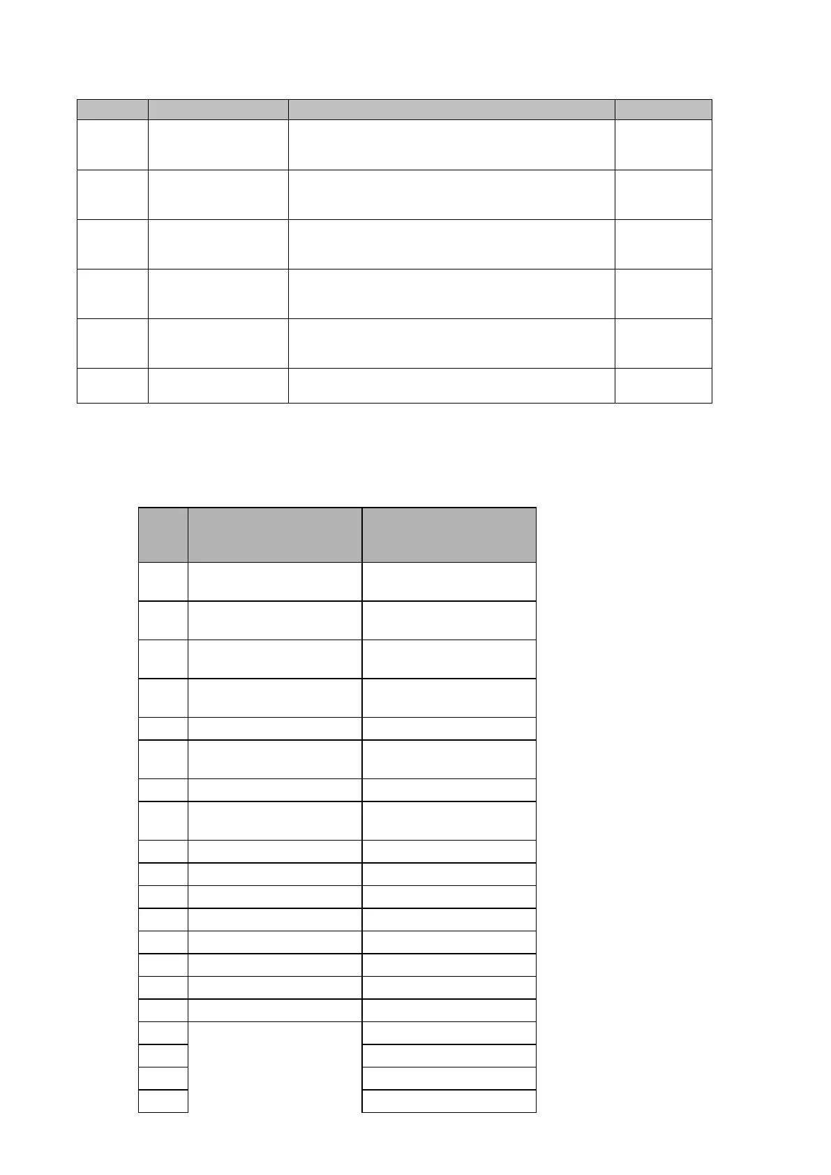
Ordinal English Text Description Source
455 LBlinder DetectBN
Load Blinder Detection in Loop BN: Cell at 1 indicates
the Impedance is located within the BN loop Load
Blinder Region.
PSL (OUT)
Distance
456 LBlinder DetectCN
Load Blinder Detection in Loop CN: Cell at 1 indicates
the Impedance is located within the CN loop Load
Blinder Region.
PSL (OUT)
Distance
457 LBlinder DetectAB
Load Blinder Detection in Loop AB: Cell at 1 indicates
the Impedance is located within the AB loop Load
Blinder Region.
PSL (OUT)
Distance
458 LBlinder DetectBC
Load Blinder Detection in Loop BC: Cell at 1 indicates
the Impedance is located within the BC loop Load
Blinder Region.
PSL (OUT)
Distance
459 LBlinder DetectCA
Load Blinder Detection in Loop CA: Cell at 1 indicates
the Impedance is located within the CA loop Load
Blinder Region.
PSL (OUT)
Distance
460 LB PowerSwing Power Swing Detected within Load Blinder Region
PSL (OUT)
Distance
1.2 Factory default programmable scheme logic
1.2.1 Logic input mapping
The default mappings for each of the opto-isolated inputs are as shown in the following table
(PSL are equivalent for P442 and P444):
Opto
Input
P442 Relay P444 Relay
1
Channel Receive
(Distance or DEF)
Channel Receive
(Distance or DEF)
2
Channel out of Service
(Distance or DEF)
Channel out of Service
(Distance or DEF)
3
MCB/VTS Main
(Z measurement-Dist)
MCB/VTS Main
(Z measurement-Dist)
4
Block Autoreclose (BAR)
(Lockout)
Block Autoreclose (BAR)
(Lockout)
6
Circuit breaker Manual
Close external order
Circuit breaker Manual
Close external order
8
Disable Autoreclose
(1-pole and 3-pole)
Disable Autoreclose
(1-pole and 3-pole)
10 Not allocated Not allocated
11 Not allocated Not allocated
12 Not allocated Not allocated
13 Not allocated Not allocated
14 Not allocated Not allocated
15 Not allocated Not allocated
16 Not allocated Not allocated
18 Not allocated
19 Not allocated
20 Not allocated