c
P44x/EN PL/Hb
MiCOM 40 Agile P442, P444
(PL) 6-
Opto
Input
P442 Relay P444 Relay
21 Not allocated
22 Not allocated
23 Not allocated
24 Not allocated
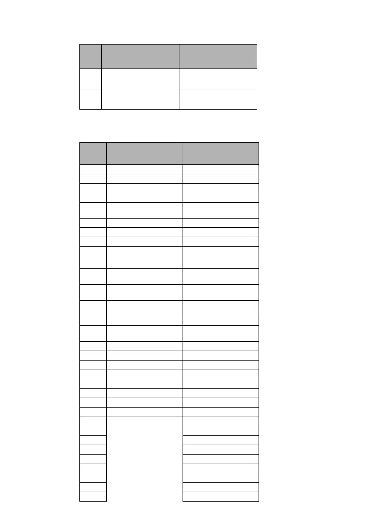
1.2.2 Relay output contact mapping
The default mappings and conditioning for each of the relay output contacts are shown in the
following table (PSL are equivalent for P442/444):
Relay
Contact
N°
P442 Relay P444 Relay
1 TripA+B+C & Z1 [straight] TripA+B+C & Z1 [straight]
2 Any Trip Phase A [straight] Any Trip Phase A [straight]
3 Any Trip Phase B [straight] Any Trip Phase B [straight]
4 Any Trip Phase C [straight] Any Trip Phase C [straight]
5
Signal send (Dist. or DEF)
[straight]
Signal send (Dist. or DEF)
[straight]
6 Any Protection Start [straight]
Any Protection Start [straight]
7 Any Trip [straight] Any Trip [straight]
8 General Alarm [straight] General Alarm [straight]
9
DEF A+B+C Trip + IN>2Trip
+ IN>3Trip
[straight]
DEF A+B+C Trip + IN>2Trip
+ IN>3Trip
[straight]
10
Dist. Trip & Any Zone & Dist
Unb CR [straight]
Dist. Trip & Any Zone & Dist
Unb CR [straight]
11
Autoreclose lockout
[straight]
Autoreclose lockout
[straight]
12
Autoreclose 1P + 3P
cycle in progress [straight]
Autoreclose 1P + 3P
cycle in progress [straight]
13 A/R Close [straight] A/R Close [straight]
14
Power Swing Detected
[straight]
Power Swing Detected
[straight]
15 Not allocated Not allocated
16 Not allocated Not allocated
17 Not allocated Not allocated
18 Not allocated Not allocated
19 Not allocated Not allocated
20 Not allocated Not allocated
21 Not allocated Not allocated
22 Not allocated Not allocated
23 Not allocated
24 Not allocated
25 Not allocated
26 Not allocated
27 Not allocated
28 Not allocated
29 Not allocated
30 Not allocated
31 Not allocated
 Loading...


