P44x/EN AP/Hb
MiCOM P40 Agile P442, P444
(AP) 5-
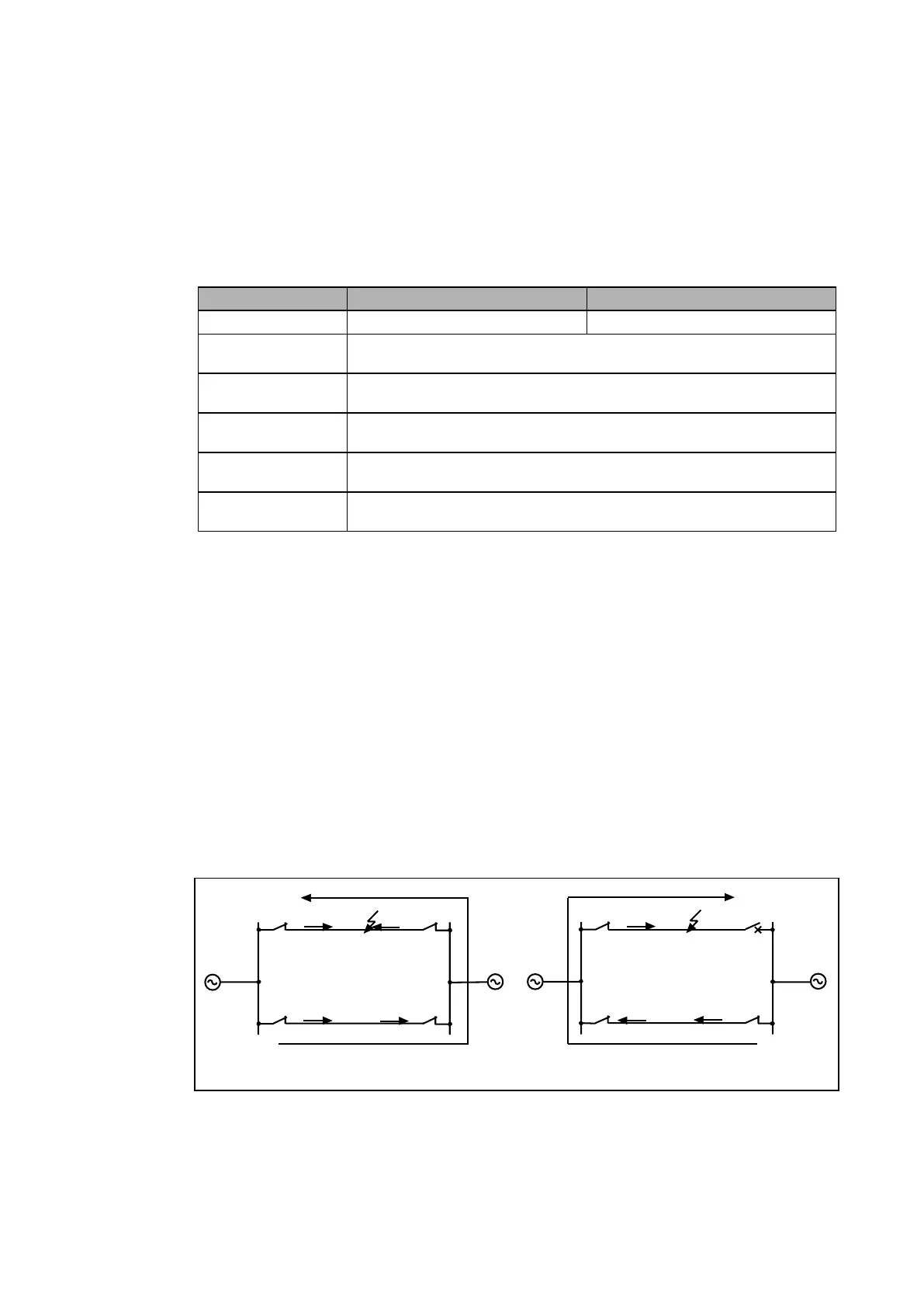
• CsZ1, CsZ2 and CsZ4 = Carrier send for zone 1, zone 2 or zone 4,
• Reverse' = Reverse Fault detected,
• Z1 to Z4 = Zone 1 to 4 decision (blocked by Power swing or Reversal guard),
• WI_CS = Weak infeed carrier send (Echo)
3.2.4 Distance Carrier Received (Dist CR)
The aided scheme options on Distance carrier receipt are shown in the next table:
None None To configure a Basic scheme.
PermZ1
To configure a Permissive scheme where Zone 1 can only trip if a Distance
Carrier is received.
PermZ2
To configure a Permissive scheme where Zone 2 can trip without waiting for
tZ2 timeout if a Distance Carrier is received.
PermFwd
To configure a Permissive scheme where any forward distance zone start will
cause an aided trip if a Distance Carrier is received.
BlkZ1
To configure a Blocking scheme where Zone 1 can only trip if a Distance
Carrier is NOT received.
BlkZ2
To configure a Blocking scheme where Zone 2 can trip without waiting for tZ2
timeout if a Distance Carrier is NOT received.
Table 4: Aided scheme options on distance carrier receipt
3.2.5 Current reversal guard logic
Where appropriate, the tReversal Guard and ‘Aid Dist Delay’ (
transmission time in blocking
scheme
) time-delays (in the case of a blocking scheme covering the transmission time)
settings will appear in the relay menu. Further customising of distance schemes can be
achieved using the Programmable Scheme Logic to condition send and receive logic.
For double circuit lines, the fault current direction can change in one circuit when circuit
breakers open sequentially to clear the fault on the parallel circuit. The change in current
direction causes the overreaching distance elements to see the fault in the opposite direction
to the direction in which the fault was initially detected (settings of these elements exceed
150% of the line impedance at each terminal). The race between operation and resetting of
the overreaching distance elements at each line terminal can cause the Permissive
Overreach, and Blocking schemes to trip the healthy line. A system configuration that could
result in current reversals is shown in Figure 36. For a fault on line L1 close to circuit breaker
B, as circuit breaker B trips it causes the direction of current flow in line L2 to reverse.
A
C
B
D
A B
FaultFault
Strong
source
Weak
source
L1
L2
L1
L2 C D
P3067EN
t2(D)
t2(C)
Note how after circuit breaker B on line L1 opens
the direction of current flow in line L2 is reversed.
Figure 36: Current reversal in double circuit lines
The basic unblocking / blocking logic scheme is detailed in section 3.5.1.2.
3.2.5.1 Permissive Overreach Schemes Current Reversal Guard
The current reversal guard incorporated in the POP scheme logic is initiated when the
reverse looking Zone 4 elements operate on a healthy line. Once the reverse looking Zone 4
elements have operated, the relay’s permissive trip logic and signal send logic are inhibited