44x/EN PL/Hb6
-54 MiCOM 40 Agile
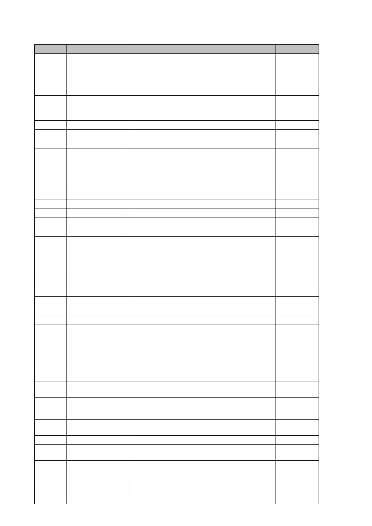
Ordinal English Text Description Source
1074 V>2 Timer Block
Block phase overvoltage stage 2 time delay
Set to 1: 'V>2 Time Delay' will be blocked and V>2 will
start but will not issue any trip command.
Reset to 0: Opto input power off if signal assigned to
an opto input OR DDB at 0 if signal assigned to a DDB
cell
PSL (IN) V>2
298 V>2 Trip Overvoltage 2
nd
stage 3-phase 2 trip
PSl (OUT)
Overvoltage
406 V>3 Start Overvoltage stage 3 start PSL
408 V>3 Start A Overvoltage phase A stage 3 start PSL
409 V>3 Start B Overvoltage phase B stage 3 start PSL
410 V>3 Start C Overvoltage phase C stage 3 start PSL
1075 V>3 Timer Block
Block phase overvoltage stage 3 time delay
Set to 1: 'V>3 Time Delay' will be blocked and V>3 will
start but will not issue any trip command.
Reset to 0: Opto input power off if signal assigned to
an opto input OR DDB at 0 if signal assigned to a DDB
cell
PSL (IN) V>3
414 V>3 Trip Overvoltage stage 3 trip PSL
407 V>4 Start Overvoltage stage 4 start PSL
411 V>4 Start A Overvoltage phase A stage 4 start PSL
412 V>4 Start B Overvoltage phase B stage 4 start PSL
413 V>4 Start C Overvoltage phase C stage 4 start PSL
1076 V>4 Timer Block
Block phase overvoltage stage 4 time delay
Set to 1: 'V>4 Time Delay' will be blocked and V>4 will
start but will not issue any trip command.
Reset to 0: Opto input power off if signal assigned to
an opto input OR DDB at 0 if signal assigned to a DDB
cell
PSL (IN) V>4
415 V>4 Trip Overvoltage stage 4 trip PSL
213 V3< Alarm Third undervoltage stage Alarm PSL(IN)
215 V3> Alarm Third overvoltage stage Alarm PSL(IN)
214 V4< Alarm Fourth undervoltage stage Alarm PSL(IN)
216 V4> Alarm Fourth overvoltage stage Alarm PSL(IN)
205 Val/Fail Acq Al.
Relays with IEC 61850 9-2 Ethernet board only with
software version up to D4.x
Alarm NCIT (9-2 Ethernet) - Frame from Merge Units
failed.
Any Logical Node is synchronized with Internal (local)
synchronization
PSL (OUT)
1224 Virtual Input 1
Goose input n° 1 - Allows binary signals that are
mapped to virtual inputs to interface into PSL
SW
1225 to
1287
Virtual Input 2 to
Virtual Input 64
Goose input n° 2 to
Goose input n° 32
SW
512 Virtual output 1
Goose output n° 1 - Allows user to control a binary
signal which can be mapped via SCADA protocol
output to other devices
PSL
513 to
543
Virtual output 2
Virtual output 32
Goose output n° 2 to
Goose output n° 32
PSL
389 VN>1 Start Neutral overvoltage stage 1 pick up PSL
1077 VN>1 Timer Block Block earth overvoltage stage 1 time delay
PSL (IN)
VN>1
391 VN>1 Trip Neutral overvoltage stage 1 trip PSL
390 VN>2 Start Neutral overvoltage stage 2 pick up PSL
1078 VN>2 Timer Block Block earth overvoltage stage 2 time delay
PSL (IN)
VN>2
392 VN>2 Trip Neutral overvoltage stage 2 trip PSL
 Loading...


