c
P44x/EN PL/Hb
MiCOM 40 Agile P442, P444
(PL) 6-
1.2.3 Programmable LED output mapping
The default mappings for each of the programmable LEDs are as shown in the following
table:
LED
No.
P442 Relay P444 Relay
1 Any Trip A Any Trip A
2 Any Trip B Any Trip B
3 Any Trip C Any Trip C
4 Any Start Any Start
5 Z1+Aided Trip Z1+Aided Trip
6 Dist Fwd Dist Fwd
7 Dist Rev Dist Rev
8 A/R Enable A/R Enable
Note: All the LEDs are latched in the default PSL.
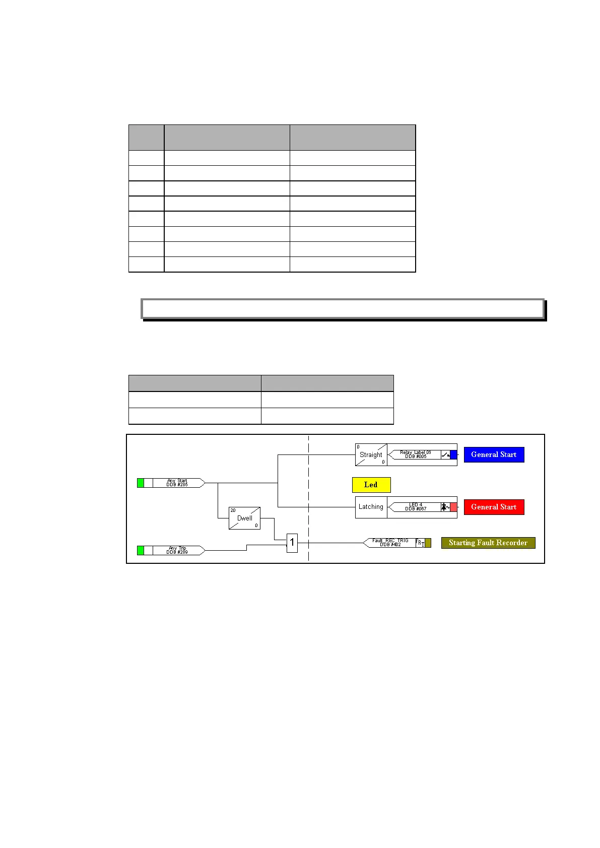
1.2.4 Fault recorder trigger
The default PSL trigger which initiates a fault record is shown in the following table:
Any Start Any Start
If the fault recorder trigger is not assigned in the PSL, no Fault recorder can be initiated and
displayed in the list by the LCD front panel.