Hb6
-12
MiCOM P40 Agile P442, P444
FAULT AND DISTURBANCE RECORDS
Accuracy
Time and date stamping:
±2 ms of applied fault/event
Fault clearance time: ±2%
CB operating time: ±5ms
Protection operating time: ±2%
Waveshape:
Comparable with applied quantities,
±5% of applied quantities
Trigger positions: ±2%
Record length: 8 records each of 1.8 s
duration (1.5 s at 60 Hz)
FAULT LOCATOR
Accuracy
Fault location: ±2% of line length (under
reference conditions)*
* Reference conditions solid fault applied on
line.
REFERENCE CONDITIONS
Ambient temperature: 20°C
FREQUENCY TRACKING RANGE
45 to 65 Hz
BREAKER FAILURE
Accuracy
Reset time < 40 ms ±2%
Thresholds: settings ±5%
Ethernet data
(where applicable)
10 Base T /100 Base TX Communications
Interface in accordance with IEEE802.3 and
IEC 61850
Isolation 1.5 kV
Cable type: Screened twisted pair STP
Max length: 100 m
100 Base FX Interface
Interface in accordance with IEEE802.3 and
IEC 61850
Wavelength: 1300 nm
Fibre: multi-mode 50/125 µm or 62.5/12 5 µm
Connector style: ST
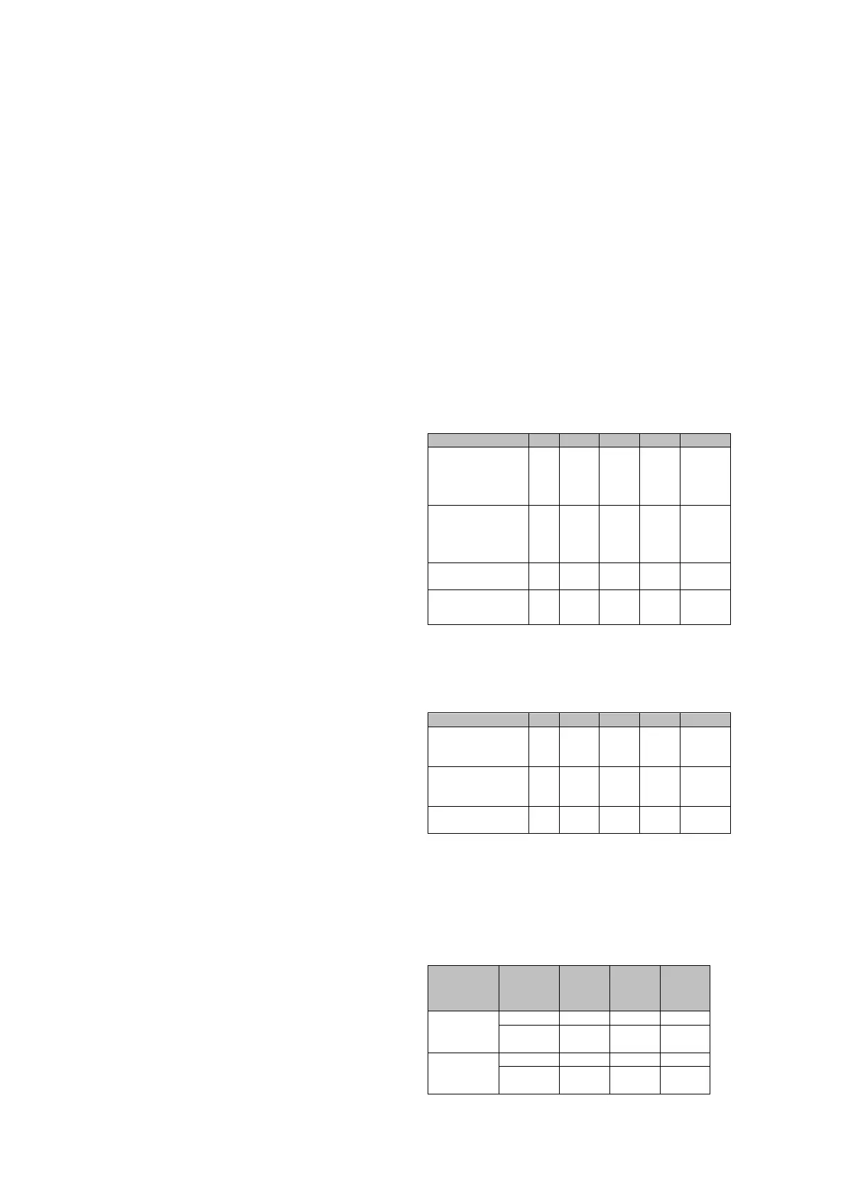
Transmitter Optical Characteristics
(TA = 0°C to 70°C, VCC = 4.75 V to 5.25 V)
BOL= Beginning of Life, EOL= End of Life
Power
BOL 62.5/125 µm,
NA = 0.275 Fiber
PO
-19
-20
-16.8 -14
dBm avg.
Power
BOL 50/125 µm,
NA = 0.20 Fiber
PO
-22.5
-23.5
-20.3 -14
dBm avg.
Optical Extinction
%
Power at
PO
(“0”)
-45
dBm avg.
BOL – Beginning of life
EOL – End of life
Receive Optical Characteristics
(TA = 0°C to 70°C, VCC = 4.75 V to 5.25 V)
Input Optical
Power Minimum at
Window Edge
Min.
-33.5 –31
Input Optical
Power Minimum at
Eye Center
Min.
-34.5 -31.8 Bm avg.
Input Optical
Power Maximum
-14 -11.8
InterMiCOM
64
fiber optic
teleprotection
(where applicable)
End-end operation: Table below shows bit
transfer time (for multiplexed links, ‘MUX’
denotes the multiplexer delay).
IM64 Cmd Applic.
Typical
Delay
Note
Permissive
Via MUX
≤
Dir. Intertrip
Via MUX
BER – Bit Error Rate for Channel