P74x/EN ST/N
1, P742, P743
(ST) 4-
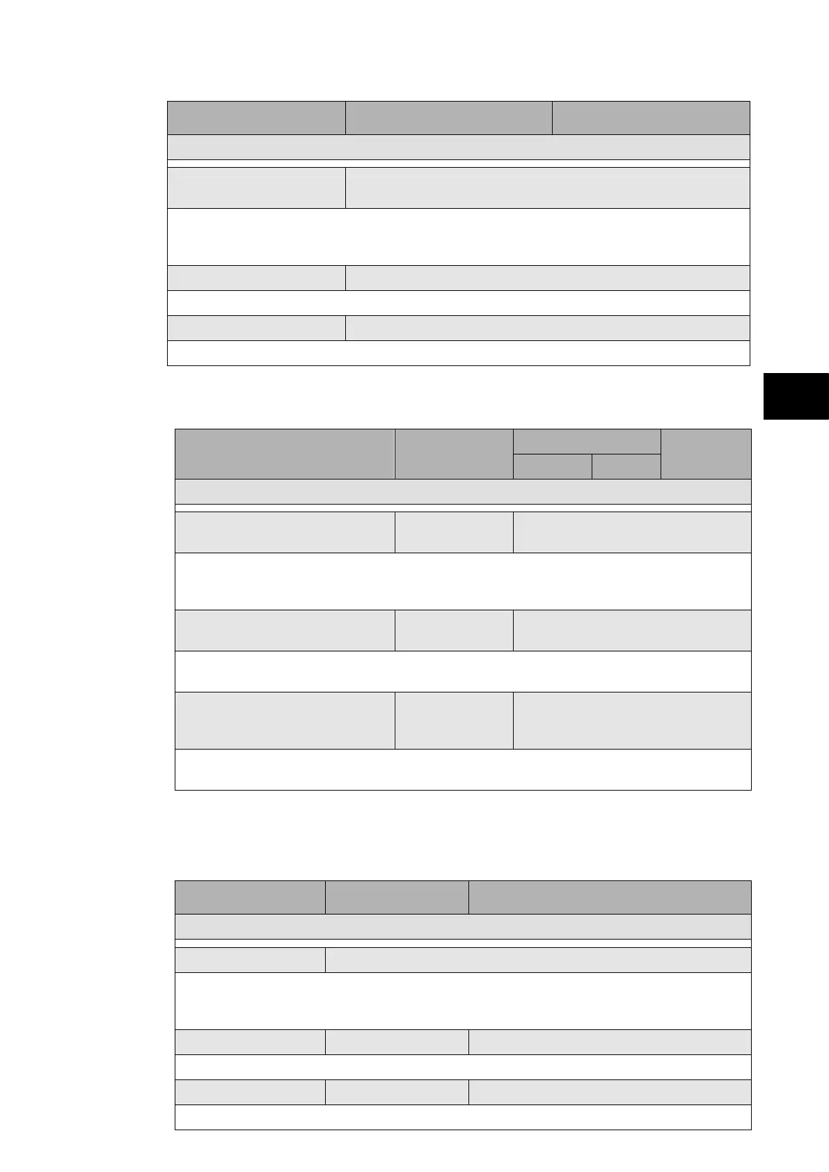
Menu Text Default Setting Available Settings
COMMISSION TESTS
Green LED Status
(P743 only)
000000000000000000
This cell is an eighteen bit binary string that indicates which of the user-programmable
LEDs on the relay are illuminated with the Green LED input active when accessing the relay
from a remote location, a ‘1’ indicating a particular LED is lit and a ‘0’ not lit.
DDB 31 - 0 11111111111111111111111111111111
Displays the status of DDB signals 0 – 31.
DDB 2047 - 2016 11111111111111111111111111111111
Displays the status of DDB signals 2016 – 2047.
1.3.7 Opto configuration (“Opto Config” column)
Menu Text Default Setting
Setting Range
Step Size
Min. Max.
OPTO CONFIG.
Global Nominal V 48/54V
24/27V, 30/34V, 48/54V, 110/125V,
220/250V, Custom
Sets the nominal battery voltage for all opto inputs by selecting one of the five standard
ratings in the Global Nominal V settings. If Custom is selected then each opto input can
individually be set to a nominal voltage value.
Opto Input 1 48/54V
24/27V, 30/34V, 48/54V, 110/125V,
220/250V
Each opto input can individually be set to a nominal voltage value if custom is selected for
the global setting.
Opto Input 2 – 8 (P741)
Opto Input 2 – 16 (P742)
Opto Input 2 – 24 (P743)
48/54V
24/27V,
30/34V, 48/54V, 110/125V,
220/250V
Each opto input can individually be set to a nominal voltage value if custom is selected for
the global setting.
1.3.8 Control input setting (“Control input” column)
The P74x offers 32 control inputs which can be set or reset locally or remotely.
This column is visible when the “Control Inputs” setting (“Configuration” column) = “visible”.
Menu Text Default Setting Available Setting
CTRL INPUTS
Ctrl I/P Status 00000000000000000000000000000000
Displays the status of the opto inputs: “0” = Reset and “1” = Set.
The control inputs can also be set and reset by setting a “1” to set or “0” to reset a control
input.
Control Input 1 No Operation Set / Reset / No Operation
Sets or resets control input 1.
Control Input 2 to 32 No Operation Set / Reset / No Operation
Sets or resets control inputs 2 to 32 individually.
 Loading...


