P74x/EN TD/N
1, P742, P743 (TD) 2-
IEC 61850 Ethernet data
10 Base T/100 Base TX Communications
Interface in accordance with IEEE802.3 and
IEC61850
Isolation 1.5kV
Cable type: Screened twisted pair STP
Max length: 100m
100 Base FX Interface
Interface in accordance with IEEE802.3 and
IEC61850
Wavelength: 1300nm
Fibre: multi-mode 50/125µm or 62.5/125µm
Connector style: ST
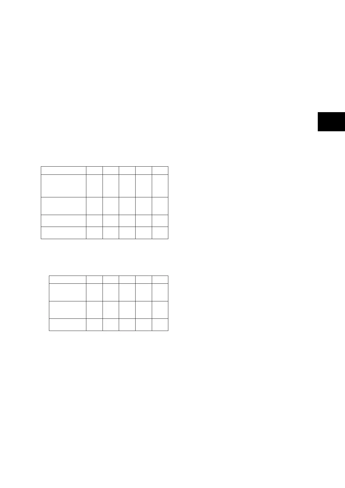
Transmitter Optical Characteristics
(TA = 0°C to 70°C, VCC = 4.75 V to 5.25 V)
Parameter Sym Min. Typ. Max Unit
Output Optical Power
BOL: 62.5/125 µm,
P
OUT
–19
–20
–16.8 –14
dBm
avg.
Output Optical Power
BOL: 50/125 µm,
P
OUT
–22.5
–23.5
–20.3 –14
dBm
avg.
10
%
Output Optical Power
at Logic “0” State
OUT
(“0”)
–45
avg.
BOL – Beginning of life
EOL – End of life
Receiver Optical Characteristics
(T
A = 0°C to 70°C, VCC = 4.75 V to 5.25 V)
Parameter Sym Min. Typ. Max. Unit
Input Optical
Power Minimum
at Window Edge
IN
(W)
–33.5 –31
dBm
avg.
Input Optical
Power Minimum
at Eye Center
IN
(C)
–34.5 –31.8
dBm
avg.
Input Optical
Power Maximum
IN
–14 –11.8
Note: The 10BaseFL connection will no
longer be supported as IEC 61850
does not specify this interface
Reference conditions
Ambient temperature: 20 °C
Frequency Tracking Range
45 to 65 Hz
Breaker failure
Accuracy
Reset time
= 25 ms from:
start to [(TBF2 or TBF4) - 30ms]
= 15 ms from:
[(TBF2 or TBF4) - 30ms] to [TBF2 or TBF4]
±2 % or 10 ms whichever is greater
Thresholds: settings ±5 % or 10 mA Whichever
Is Greater
Protection functions
Global Settings (System Data)
Language: English/French/German/Spanish
Frequency: 50/60 Hz
Common conventional ratios (CU)
Primary basis current (virtual)
Ibp: 1000A
Current transformers (PU)
Phase CT Primary: 1…30.000A (step 1A)
Phase CT Secondary In: 1A or 5A
Phase Fault elements (CU)
Phase current slope adjustment
k2: 0.20…0.90 (step 0.1)
Phase differential current threshold
ID>2: 50A…30kA (step 10A)
Check Zone slope adjustment
kCZ: 0.00…0.90 (step 0.01)
Check Zone differential current threshold
IDCZ >2: 50A…30kA (step 10A)
Circuitry fault slope adjustment
ID>1: 10…500A (step 10A)
Circuitry fault threshold
k1: 0.00…0.50 (step 0.01)
Circuitry fault alarm timer
ID>1 tCF: 0.1…600.0s (step 0.1s)
Sensitive earth fault
Option for high neutral impedance:
Disabled/Enabled
Threshold for sensitive Earth fault with flowing
current control:
IbiasPh>Cur.: 50A…30kA (step 10A)
Residual current slope adjustment
kN2: 0.00…0.90 (step 0.01)
Residual differential current threshold:
IDN>2: 10A…30kA (step 10A)
Residual Check Zone current slope adjustment
kNCZ: 0.00…0.90 (step 0.01)
Residual Check Zone differential current
threshold:
IDNCZ>2: 10A…30kA (step 10A)
Circuitry fault slope adjustment
kN1: 0.00…0.50 (step 0.01)
Circuitry fault threshold:
IDN>1: 10…500A (step 10A)
Circuitry fault alarm timer
IDN>1 tCF: 0.1…600.0s (step 0.1s)
 Loading...


