x/EN ST/Na7
-
MiCOM P74
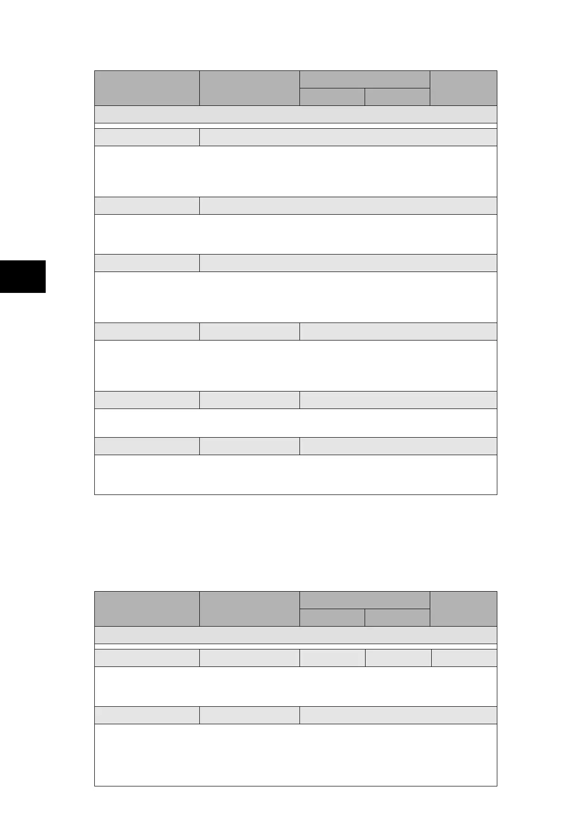
Menu Text Default Setting
Setting Range
Step Size
Min. Max.
INTERMICOM COMMS
Message Status OK / Fail / Absent / Unavailable
Indicates when the percentage of received valid messages has fallen below the
“IM Msg Alarm Lvl” setting within the alarm time period.
OK = acceptable ratio of lost messages, FAIL = unacceptable ratio of lost messages,
Absent = InterMiCOM board is not fitted, Unavailable = hardware error present
Channel Status OK / Fail / Absent / Unavailable
Indicates the state of the InterMiCOM communication channel
OK = channel healthy, FAIL = channel failure, Absent = InterMiCOM board is not fitted,
Unavailable = hardware error present
IM H/W Status OK / Fail / Absent / Unavailable
Indicates the state of the InterMiCOM hardware
OK = InterMiCOM hardware healthy, Read Error =
InterMiCOM hardware failure, Write
Error =
InterMiCOM hardware failure, Absent = InterMiCOM board is either not fitted or
failed to initialise
Loopback mode Disabled Disabled / Internal / External
By selecting “Loopback Mode” to “Internal”, only the internal software of the relay is
checked whereas “External” will check both the software and hardware used by
InterMiCOM (In the latter case, it is necessary to connect the transmit and receive pins
together and ensure that the DCD signal is held high).
Test pattern 11111111 00000000 / 11111111
A test pattern can be entered which is then transmitted through the software and/or
hardware.
Loopback Status
Providing all connections are correct and the software is working correctly, the “Loopback
Status” cell will display “OK”. An unsuccessful test would be indicated by “FAIL”, whereas a
hardware error will be indicated by “UNAVAILABLE”.
1.3.10.2 InterMiCOM configuration
The “INTERMICOM CONF” column selects the format of each signal and its fallback
operation mode.
InterMiCOM provides 8 commands over a single communications link, with the mode of
operation of each command being individually selectable within the “IM# Cmd Type” cell (# =
1 to 8).
Menu Text Default Setting
Setting Range
Step Size
Min. Max.
INTERMICOM CONF
IM Msg Alarm Lvl 25% 0% 100% 1%
The “IM ¨Msg Alam Lvl” sets the level of invalid messages received compared to the total
number of messages that should have been received. If this value exceeds the selected
level, an alarm will be raised.
IM1 Cmd type Blocking Disabled / Blocking / Direct / Permissive
“Blocking” mode provides the fastest signalling speed (available on commands 1 – 4),
“Direct Intertrip” mode provides the most secure signalling (available on commands 1 – 8)
and “Permissive” mode provides the most dependable signalling (available on commands
5 – 8).
Each command can be disabled so that it has no effect in the logic of the relay.
 Loading...


