(GS) 3-
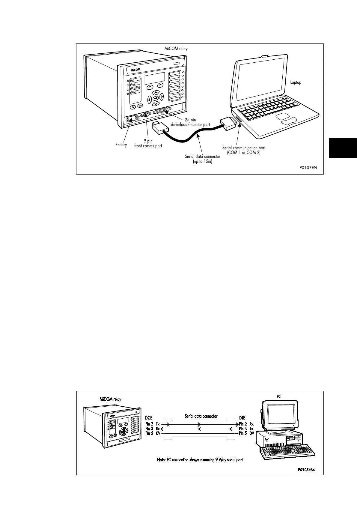
FIGURE 9: FRONT PORT CONNECTION
The relay is a Data Communication Equipment (DCE) device. Thus the pin connections of
the relay’s 9-pin front port are as follows:
Pin no. 2 Tx Transmit data
Pin no. 3 Rx Receive data
Pin no. 5 0V Zero volts common
None of the other pins are connected in the relay. The relay should be connected to the
serial port of a PC, usually called COM1 or COM2. PCs are normally Data Terminal
Equipment (DTE) devices which have a serial port pin connection as below (if in doubt check
your PC manual):
25 Way 9 Way
Pin no. 2 3 2 Rx Receive data
Pin no. 3 2 3 Tx Transmit data
Pin no. 5 7 5 0V Zero volts common
For successful data communication, the Tx pin on the relay must be connected to the Rx pin
on the PC, and the Rx pin on the relay must be connected to the Tx pin on the PC, as shown
in Figure 10. Therefore, providing that the PC is a DTE with pin connections as given above,
a ‘straight through’ serial connector is required, i.e. one that connects pin 2 to pin 2, pin 3 to
pin 3, and pin 5 to pin 5. Note that a common cause of difficulty with serial data
communication is connecting Tx to Tx and Rx to Rx. This could happen if a ‘cross-over’
serial connector is used, i.e. one that connects pin 2 to pin 3, and pin 3 to pin 2, or if the PC
has the same pin configuration as the relay.
 Loading...


