(GS) 3-
LED
Number
LED Input Connection/Text Latched P74x LED Function Indication
14
FnKey LED6 Red
FnKey LED6 Yellow
FnKey LED6 Green
No Not used
15
FnKey LED7 Red
FnKey LED7 Yellow
FnKey LED7 Green
No Not used
16
FnKey LED8 Red
FnKey LED8 Yellow
FnKey LED8 Green
No Not used
17
FnKey LED9 Red
FnKey LED9 Yellow
FnKey LED9 Green
No Not used
18
FnKey LED10 Red
FnKey LED10 Yellow
FnKey LED10 Green
No Not used
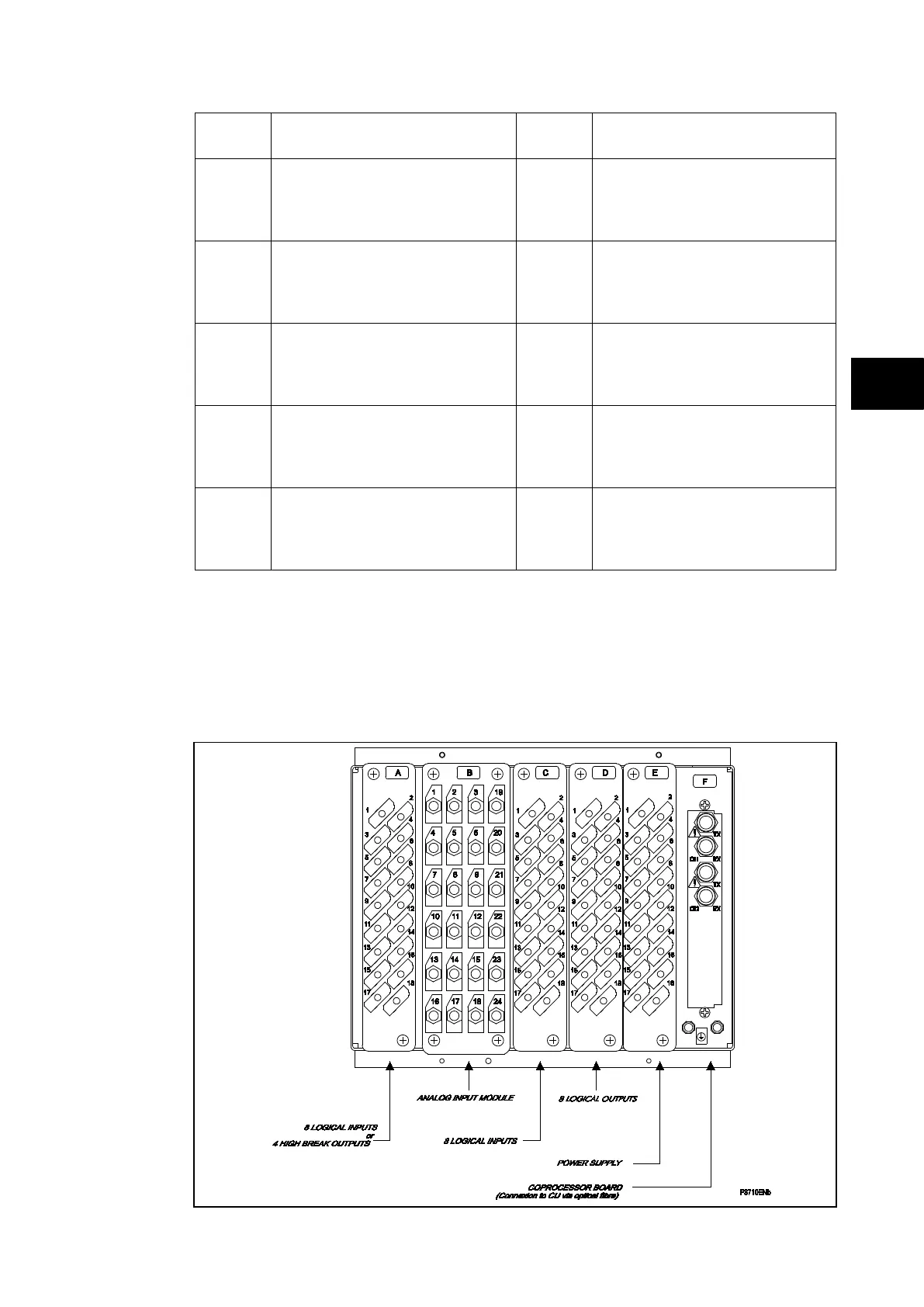
1.2.2 Relay rear panel
Examples of the rear panel of the relay are shown in Figures 3, 4 and 5. All current signals,
digital logic input signals and output contacts are connected at the rear of the relay. Also
connected at the rear is the twisted pair wiring for the rear EIA(RS)485 communication port;
the IRIG-B time synchronising input is optional in the P741, the Ethernet rear communication
board with copper and fiber optic connections or the second communication and InterMiCOM
board are optional in the P741 and P743.
FIGURE 3: P742 RELAY REAR VIEW 40TE