CM
4.2.9 Current differential communications
This test verifies that the P742 or P743 relay’s fibre optic communications ports used for
communications to the P741 Central Unit, are operating correctly.
1T
O7
COMMUNICA
TION
BOARDS
OPTIONAL BOARD
CO-PROCESSOR BOARD
POWER SUPPLY MODULE
P3712ENc
LOGICAL OUTPUT CONTACT BOARD
LOGICAL INPUT CONTACT BOARD
A
GB C D E F H
J
K
TX
RX
SK6
LINK
ACTIVITY
00.02.84.9F
.FF.90
R
20148098
xWorks
IRIG-B12x
WindRiver
R
RX
CH1
RX
CH2
TX
L
TX
M N
15
13
17
16
18
12
14
5
7
9
11
8
10
6
4
1
3
2
15
13
17
16
18
12
14
5
7
9
11
8
10
6
4
1
3
2
15
13
17
16
18
12
14
5
7
9
11
8
10
6
4
1
3
2
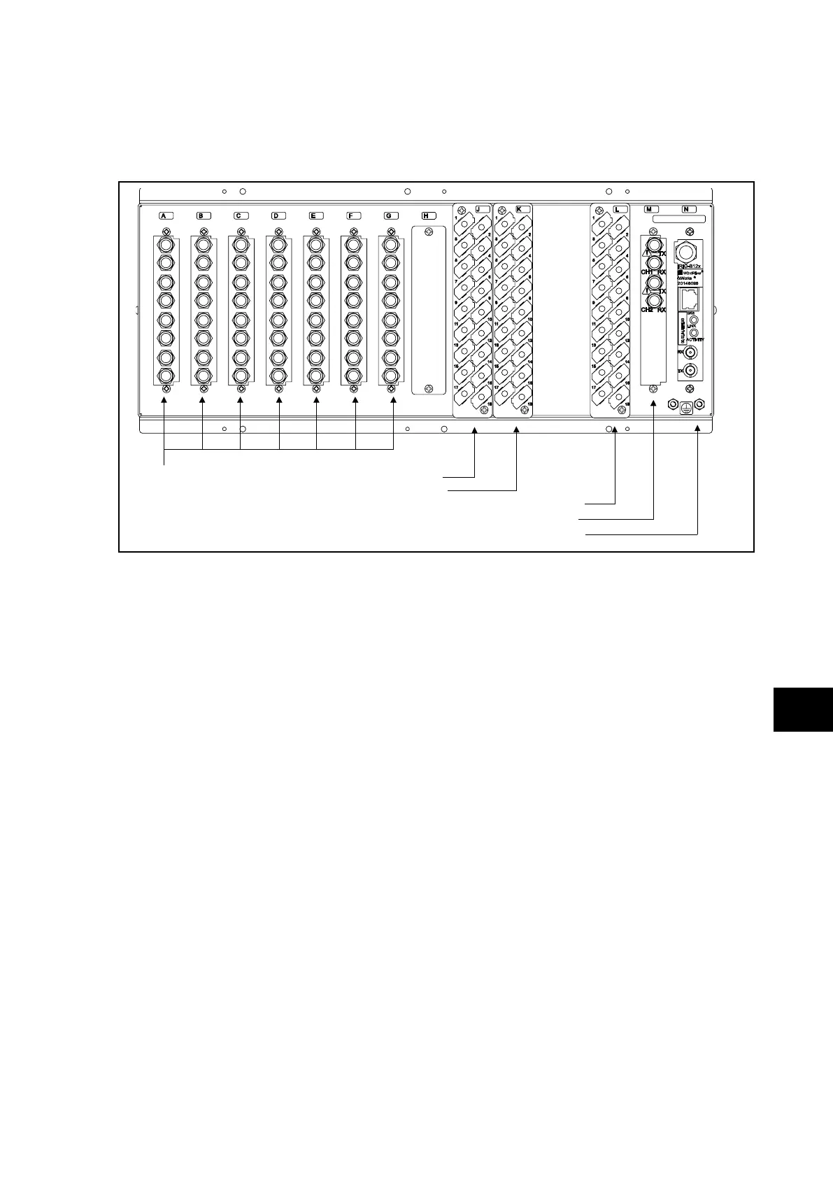
FIGURE 5: P741 REAR TERMINAL BLOCKS AND COMMUNICATION PORTS
When connecting or disconnecting optical fibres care should be taken not to look directly into
the transmit port or end of the optical fibre.
From central unit, the cell [PU CONF & STATUS, PU connected] displayed the list of
peripheral units connected to the central unit.
From peripheral unit, it is possible to check the communication with the central unit by
disconnecting the optical fibre, an alarm “Fibre Com Error” should appear.
4.2.10 Current inputs (P742, P743 only)
This test verifies that the accuracy of current measurement is within the acceptable
tolerances.
All relays will leave the factory set for operation at a system frequency of 50Hz.
If operation at 60Hz is required then this must be set in cell [SYSTEM DATA, Frequency].
Apply current equal to the line current transformer secondary winding rating to each current
transformer input of the corresponding rating in turn, see Table 1 or the external connection
diagrams for the appropriate terminal numbers, checking its magnitude using a multimeter.
The corresponding reading can then be checked in the relay’s MEASUREMENTS 1 column
and value displayed recorded.
The measured current values displayed on the relay LCD or a portable PC connected to the
front communication port will either be in primary or secondary Amperes. If cell [MEASURE’T
SETUP, Local Values] is set to ‘Primary’, the values displayed should be equal to the applied
current multiplied by the corresponding current transformer ratio set in the ‘CT and VT
RATIOS’ menu column (see Table 5). If cell [MEASURE’T SETUP, Local Values] is set to
‘Secondary’, the value displayed should be equal to the applied current.
 Loading...


