P74x/EN PL/N
1, P742, P743
(PL) 7-
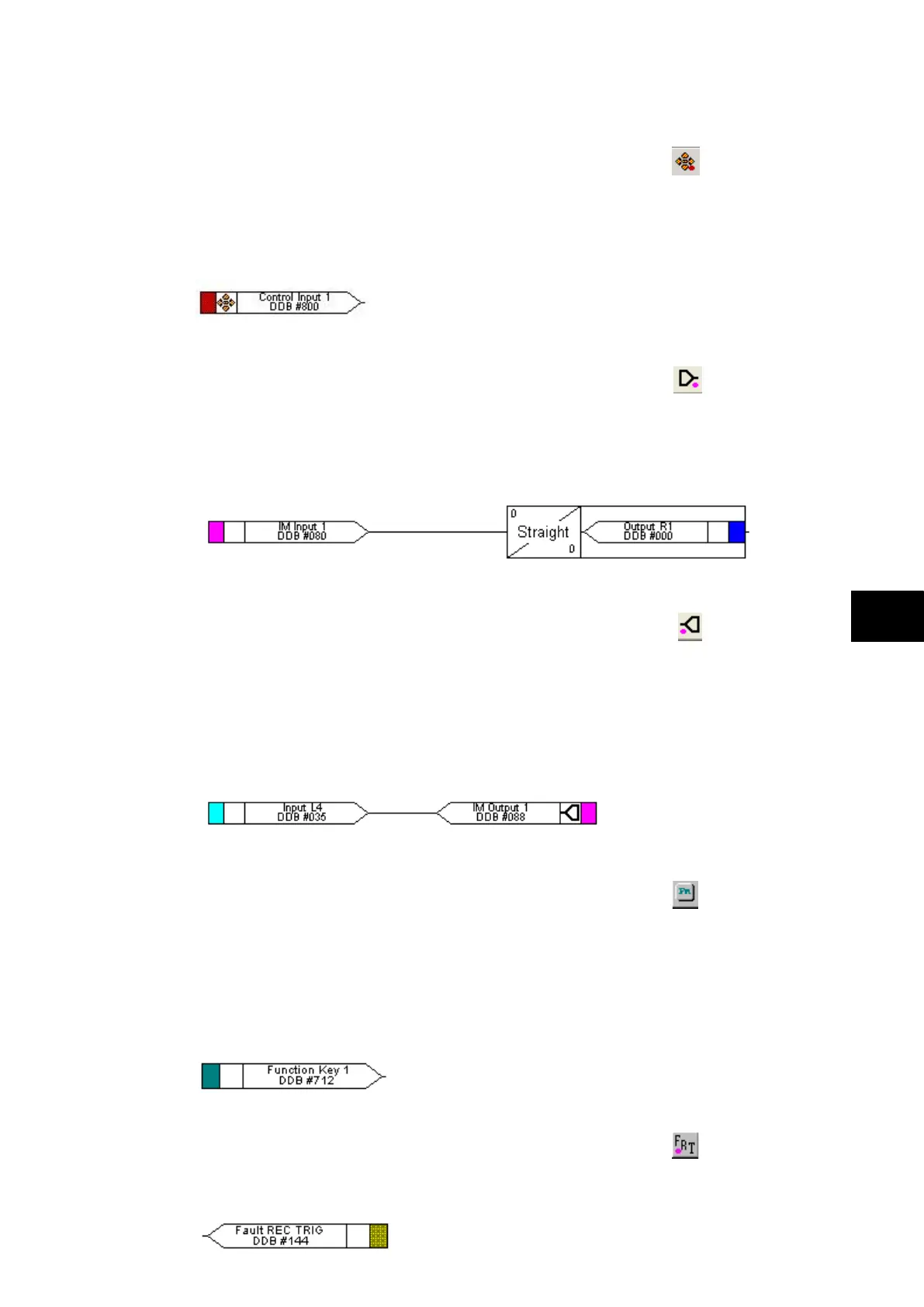
1.6.7 Control in signal properties
Control In
There are 32 control inputs which can be activated via the relay menu, ‘hotkeys’ or via rear
communications. Depending on the programmed setting i.e. latched or pulsed, an associated
DDB signal will be activated in PSL when a control input is operated.
For example operate control input 1 to assert DDB 800 in the PSL.
1.6.8 InterMiCOM In command properties
InterMiCOM In
There are 8 EIA(RS)232 InterMiCOM inputs that could be selected and used for
teleprotection. ‘InterMiCOM In’ is a received signal from remote end that could be mapped
to selected output relay or logic input.
For example, InterMiCOM Input 1 is mapped to output relay 1.
1.6.9 InterMiCOM Out command properties
InterMiCOM Out
There are 8 EIA(RS)232 InterMiCOM outputs that could be selected and used for
teleprotection. ‘InterMiCOM Out’ is a send command to a remote end that could be mapped
to any logic output or opto input. This signal will be transmitted to the remote end using
protection communication and will appear at the remote end as corresponding ‘InterMiCOM
In’ command.
For example, InterMiCOM Output 1 is mapped to opto input 4.
1.6.10 Function key properties
Function Key
Each function key can be selected and used for programming in PSL. Activation of the
function key will drive an associated DDB signal and the DDB signal will remain active
depending on the programmed setting i.e. toggled or normal. Toggled mode means the DDB
signal will remain latched or unlatched on key press and normal means the DDB will only be
active for the duration of the key press.
For example operate function key 1 to assert DDB 712 in the PSL.
1.6.11 Fault recorder trigger properties
Fault Record Trigger
The fault recording facility can be activated, by driving the fault recorder trigger DDB signal.
For example assert DDB 144 to activate the fault recording in the PSL.
 Loading...


