-
Keypad/
LCD
Courier
IEC870-5-
103
IEC
61850
Display & modification of
all settings
• •
Digital I/O signal status
• • • •
Display/extraction of
measurements
• • • •
Display/extraction of fault
records
• •
•
Extraction of disturbance
records
• • •
Programmable scheme
logic settings
•
Reset of fault & alarm
records
• • •
Clear event & fault
records
• •
Time synchronization
• • •
Control commands
• • •
Table 1
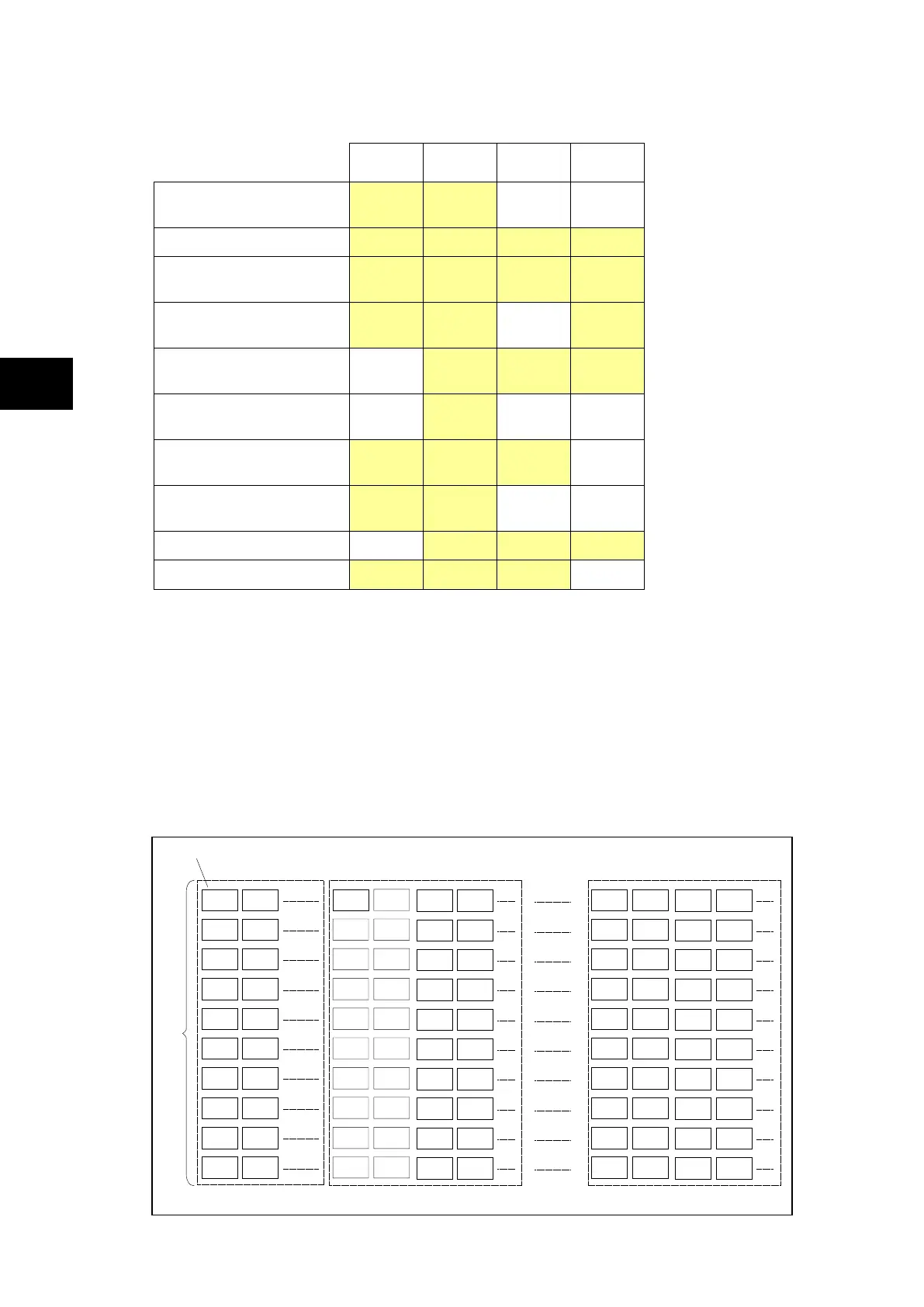
1.5 Menu structure
The relay’s menu is arranged in a tabular structure. Each setting in the menu is referred to
as a cell, and each cell in the menu may be accessed by reference to a row and column
address. The settings are arranged so that each column contains related settings, for
example all of the disturbance recorder settings are contained within the same column. As
shown in Figure 6, the top row of each column contains the heading that describes the
settings contained within that column. Movement between the columns of the menu can only
be made at the column heading level. For a complete list of all of the menu settings, see the
Settings chapter P74x/EN ST.
Colum n
dat a
settings
Column header
Contro l&suppor t
Group 1
Group 4
Up to4protectio nsettinggroups
System dat a
V
iew records
DIFF
BUSBARPROT
BUSBAR
OPTION
P0106ENb
INPUTS
LABELS
OUTPUT
LABELS
DIFF
BUSBARPROT
BUSBAR
OPTION
INPUTS
LABELS
OUTPUT
LABELS
FIGURE 6: MENU STRUCTURE