pplication Notes
P74x/EN AP/N
1, P742, P743 (AP) 6-
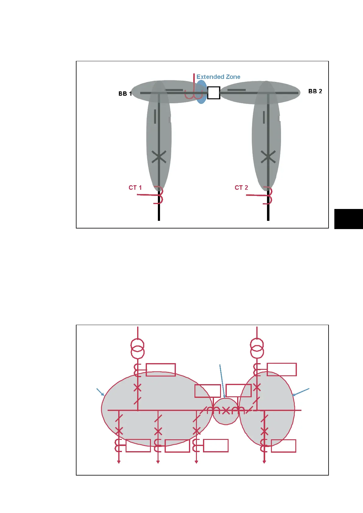
There is one zone for BB1 to CT3 and one zone for BB2 to CT3.
P0877ENa
C
T 3 is not taken into account
Coupling Open
Isolator Closed
Isolator Closed
Zone 1 = CT1
Zone 2 = CT2
Zone 1 = BB1
Zone 2 = BB2
CB Closed
CB Closed
Check Zone = CT1 + CT2
FIGURE 17: BUS COUPLER OPEN
A zone is defined from a CT to an other CT or an open electrical element (coupler CB or
isolator).
When one CT is used in the coupling and the coupler CB is open, the coupler CT
measurement is not taken into account and a zone is created from each bar feeder CT to
that open coupler CB.
There is one zone for BB1 and one zone for BB2.
6.5.3 Double bus with two CT bus coupler
P742/3
P742/3
P742/3
P742/3
P742/3
P742/3
P742/3
P742/3
P742/3
P742/3
P742/3
P742/3
P742/3
n3 4 5
1
2
n+1
BB1 BB2
n+2
Zone 1 Zone 2
Virtual Zone
(3 (fixed))
P742/3
n3 4 5
1
2
n+1
BB1 BB2
n+2
Zone 1 Zone 2
Virtual Zone
(3 (fixed))
P742/3
P742/3
FIGURE 18: BUS COUPLER CLOSED