x/EN MR/Na7
Measurements and Recording
-
MiCOM P74
2. EVENT & FAULT RECORDS
The relay records and time tags up to 512 events and stores them in non-volatile (battery
backed up) memory. This enables the system operator to establish the sequence of events
that occurred within the relay following a particular power system condition, switching
sequence etc. When the available space is exhausted, the oldest event is automatically
overwritten by the new one.
The real time clock within the relay provides the time tag to each event, to a resolution of
1ms.
The event records are available for viewing either via the front plate LCD or remotely, via the
communications port.
Local viewing on the LCD is achieved in the menu column entitled "VIEW RECORDS". This
column allows viewing of event, fault and maintenance records. Different columns exist in
the Central unit and the Peripheral Unit.
The column for the Central Unit is shown below. The column displayed in the Peripheral
Units is shown underneath.
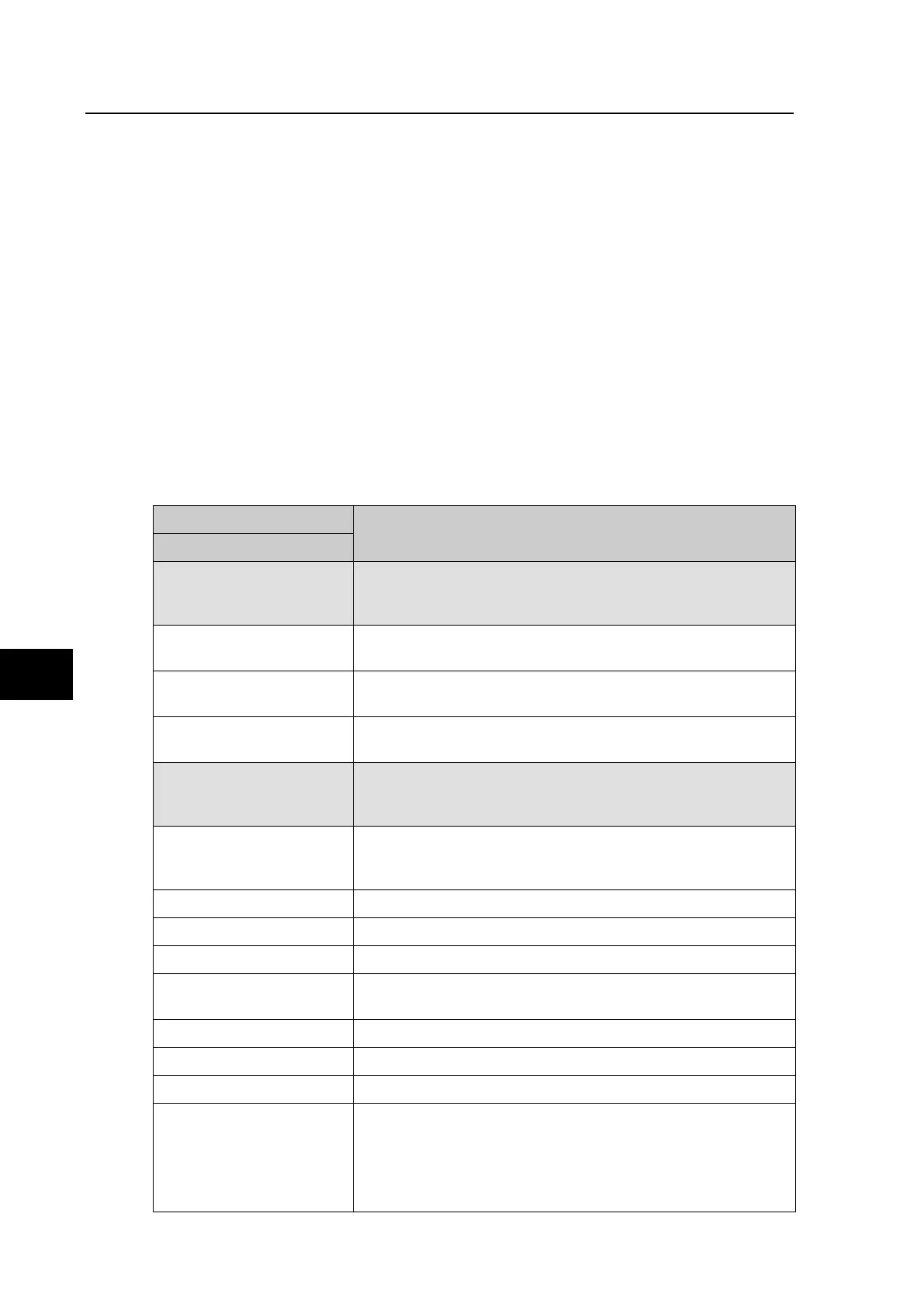
2.1 “View Recods” Column (P741)
VIEW RECORDS
Description
LCD Reference
Select Event
Setting range from 0 to 511. This selects the required event
record from the possible 512 that may be stored. A value of 0
corresponds to the latest event and so on.
Time & Date
Time & Date Stamp for the event given by the internal Real
Time Clock.
Event Text
Up to 16 Character description of the Event refer to following
sections).
Event Value
Up to 32 Bit Binary Flag or integer representative of the Event
(refer to following sections).
Select Fault
Setting range from 0 to 4. This selects the required fault
record from the possible 5 that may be stored. A value of 0
corresponds to the latest fault and so on.
The following cells show all the fault flags, protection starts,
protection trips, fault location, measurements etc. associated
with the fault, i.e. the complete fault record.
Active Group Active group when fault recorder starts
Faulted Phase Phase initiating fault recorder starts
Start Elements Note relevant for CU
Trip Elements Trip 87BB zone x, Trip 87BB block zone x, Trip 50BF zone x,
Trip 50BF block zone, Dead Zone signal, Manual trip zone.
Time Stamp Time and date of fault recorder start
Fault Alarms Yes, No
System Frequency 50.00 Hz, 60.00 Hz,
Fault duration - if fault detected by differential protection => delay between
first detection of differential current and disappearance of
differential current
- if breaker failure order received from PU => delay between
reception of order and disappearance of the current
 Loading...


