x/EN AP/Na7
-50 MiCOM P74
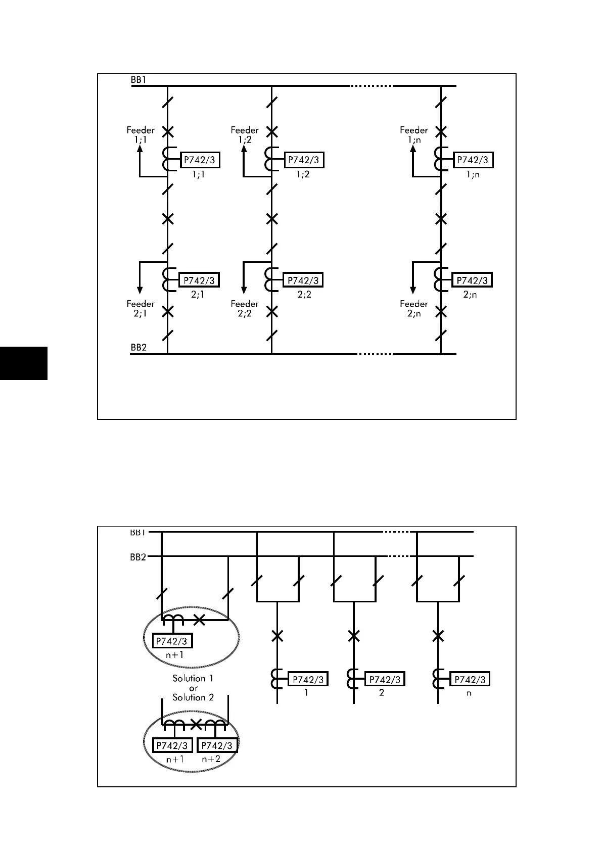
FIGURE 31: BREAKER AND A HALF SCHEME
The above example shows a breaker and a half scheme. The recommended solution is to
have two separate schemes. There are n feeders connected to each busbar.
Each scheme will require 1 central unit and n peripheral units. An other solution is to use
only one central unit and 2 x n peripheral units. The type of peripheral unit used for each
bay will depend on the i/o requirements of the bay in question.
FIGURE 32: DOUBLE BUSBAR APPLICATION WITH BUS COUPLER
 Loading...


