P74x/EN FD/N
1, P742, P743
(FD) 9-
1. RELAY SYSTEM OVERVIEW
1.1 Hardware overview
The relay hardware is based on a modular design whereby the relay is made up of an
assemblage of several modules that are drawn from a standard range. Some modules are
essential while others are optional depending on the user’s requirements.
The different modules that can be present in the relay are as follows:
1.1.1 Processor board (Main board)
The main board performs some functions for the relay (fixed and programmable scheme
logic…) and controls the operation of modules which are on its interconnection bus within the
relay. The main board also contains and controls the user interfaces (LCD, LEDs, keypad
and communication interfaces).
1.1.2 Coprocessor board
In P742 and P743, the co-processor board controls the operation of I/O modules within the
relay and manages the communication with the P741 relay.
In P741, the co-processor board controls the communication boards and manages the
communication with others P741 of the system (if present).
1.1.3 Internal Communication board
Only present within P741 relay.
The communication board manages the communication with the P742 and P743 relays.
1.1.4 Analogue Input module
The Analogue input module is only present in P742 and P743 relays. The input module
converts the information contained in the analogue or digital input signals into a format
suitable for the co-processor board. The standard input module consists of two boards:
• a Current transformer board to provide electrical isolation
• a main input board which provides analogue to digital conversion and the isolated digital
inputs.
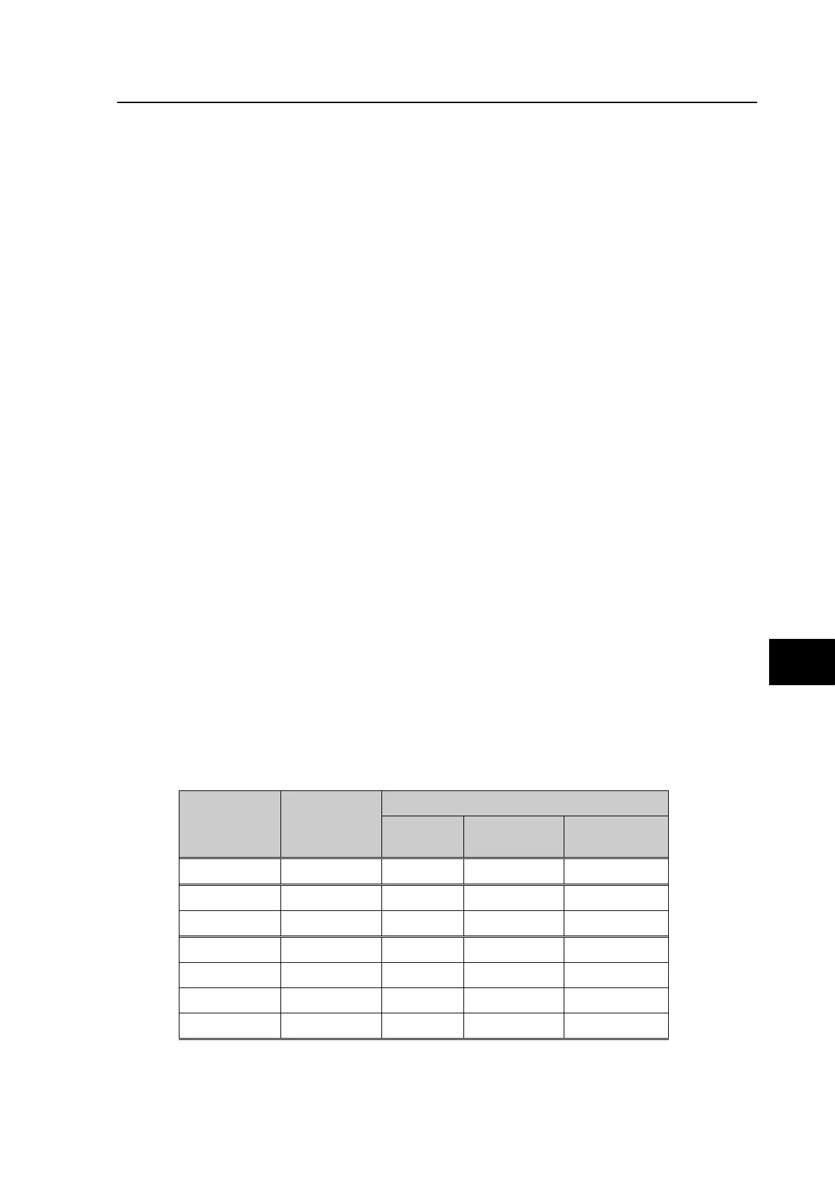
1.1.5 Input and output boards
Model Opto-inputs
Relay outputs
normally
open
change
over
High Break
P741 8 x UNI
(1)
6 2 --
P742xxxA 16 x UNI
(1)
6 2 --
P742xxxB 8 x UNI
(1)
6 2 4
P743xxxA 24 x UNI
(1)
14 2 --
P743xxxB 16 x UNI
(1)
12 4 4
P743xxxC 24 x UNI
(1)
6 2 4
P743xxxD 16 x UNI
(1)
6 2 8
(1)
Universal voltage range opto inputs n/o – normally open
c/o – change over
 Loading...


