x/EN ST/Na7
-
MiCOM P74
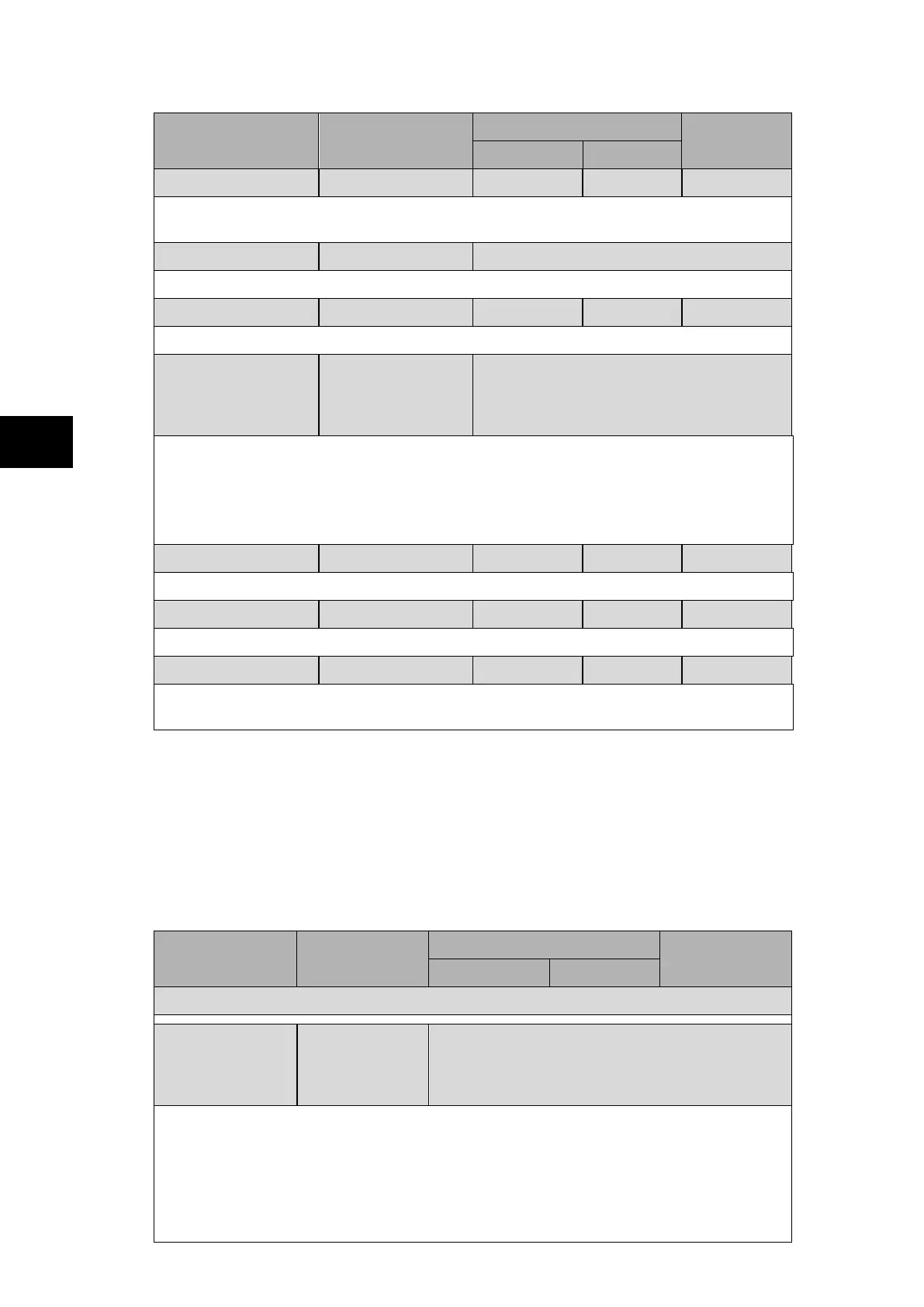
Menu Text Default Setting
Setting Range
Step Size
Min. Max.
I>1 Time Dial
7.0 0.5 15.0 0.1
Setting for the time multiplier setting to adjust the operating time of the IEEE/US IDMT
curves.
I>1 Reset Char
DT DT/Inverse
Setting to determine the type of reset/release characteristic of the IEEE/US curves.
I>1tReset
0.0 0.0 100.0 0.1
Setting that determines the reset/release time for definite time reset characteristic.
I>2 Function
Disabled Disabled / 87BBP&N blocking / High Set
I>2 / I>2 & 87BBP&N / 87BB/P blocking /
87BB/N blocking / I>2 & 87BB/P / I>2 &
87BB/N
Setting to enable or disable the second stage overcurrent element.
The overcurrent can be used as high set overcurrent, to block the 87BB protection for
phase and earth fault element (87BBP&N blocking), only the 87BB phase element
(87BB/P blocking) , only the 87BB Sensitive Earth Fault (SEF) element (87BB/N blocking),
or a combination of the different functions
I>2 Current Set 20.00* I
n
0.10* I
n
32.00* I
n
0.01* I
n
Pick-up setting for second stage overcurrent element.
I>2 Time Delay
1.00s 0.00s 100.0s 0.01s
Setting for the operating time-delay for second stage overcurrent element.
Block Drop-Off 0.3s 0.2s 6s 0.1s
Adjusts the differential busbar protection (87BB) blocking function during drop-
from 200ms to 6s.
1.2.6 Non-Directional Earth Fault Overcurrent Protection and External Fault Detection by High-Set
Overcurrent (“Earth Fault” menu – P742/P743)
The P742 and P743 relays include extra or backup non-directional earth fault protection. The
earth fault element has two stages of protection. The earth fault element needs to be co-
ordinated with any other protection elements on the system, in order to provide
discriminative fault clearance. The inverse time characteristics available for the earth fault
protection, are the same as those for the Overcurrent element.
Note: Ι
n
is the CT nominal current.
Menu Text Default Setting
Setting Range
Step Size
Min. Max.
Earth Fault
Ι
N
>1 Function
Disabled
Disabled, DT, IEC S Inverse, IEC V Inverse, IEC E
Inverse, UK LT Inverse, IEEE M Inverse, IEEE V
Inverse, IEEE E Inverse, US Inverse, US ST
Inverse
Setting for the tripping characteristic for the first stage earth fault element.
Setting choice: Disabled, definite time (DT), IEC S(tandar) Inverse, IEC V(ery) Inverse,
IEC E(xtremely) Inverse, UK L(ong) T(ime) Inverse, EUUU Moderately) inverse, IEEE
V(ery) Inverse, IEEE E(xtremely) Inverse, US Inverse or US S(hort) T(ime) Inverse.
The next menus are displayed according to the function choice (refer to P74x/EN GS
section). When Disabled, the next menu is ‘I
N
>2 Function’.
 Loading...


