GEDA
®
Temporary Construction Hoist PH 650
Operating Manual Page 56 of 64 BL148GB2017 / 11
13 Malfunctions - Diagnosis – Repair
Only have troubleshooting and fault elimination carried out
by authorised personnel trained especially for this kind of
work.
Before troubleshooting, lower the car (if possible) and
unload!
Immediately discontinue operation if faults occur that
endanger operational safety!
Electric shock
Before working on the electrical installation of the
construction hoist, switch off and lock the main switch. For
safety, disconnect the mains plug.
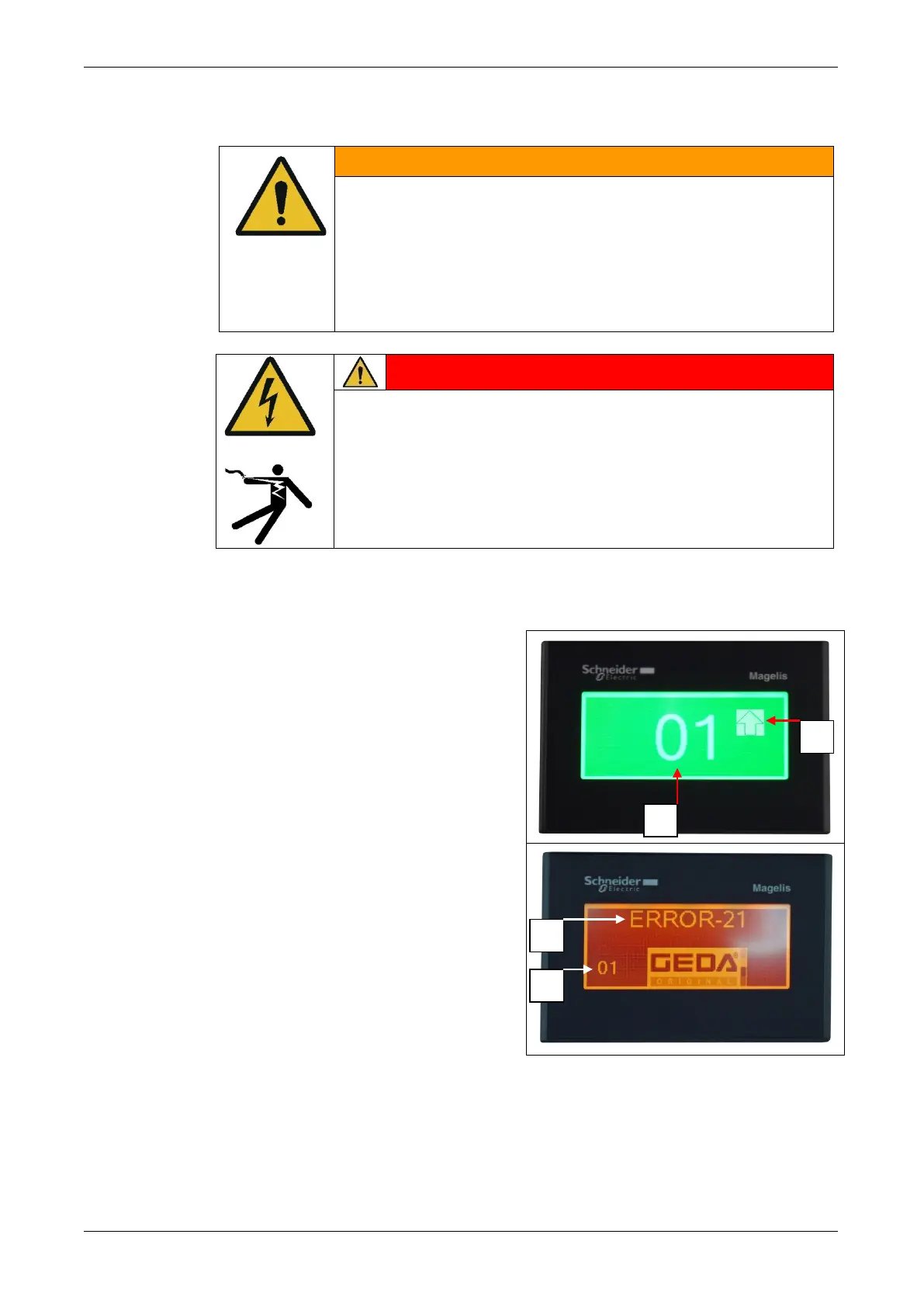
13.1 Display module
The display module indicates the
direction of travel and provides
quicker and easier identification of
the switching status of the limit
switch and errors in the system.
2 = Direction of travel indicator
3 = ERROR code
*For hoists with no landing limit-
switch approach bar installed,
00 always appears as the landing
indicator.
Actions for ERROR indications
ERROR code displayed identifies and rectifies the fault.
Wait until the control is automatically enabled.