Do you have a question about the GEDA 300Z and is the answer not in the manual?
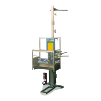
Images used refer to specific machine types, may be schematic.
Activities with specific hazards indicated by warning notices.
Details specific warnings such as electric shock, crushing, fire, and falling objects.
Warning about electric shock hazard and safety precautions.
Warning about crushing hazard and avoiding the hazard area.
Prohibition of using the hoist during fire incidents.
Warning against reaching into the machine's travel path.
Instruction to secure the machine with a padlock to prevent unintended operation.
Warning about falling tools/parts and securing them.
Warning about fall and trip hazards when entering/exiting the car.
Warning about suspended loads; do not stand under them.
Warning about access only for authorised individuals.
Instructions on wearing personal protective equipment and handling cleaning agents.
List of abbreviations used in the manual.
Publisher information, copyright, and reproduction restrictions.
Details about the machine model and year of manufacture.
Information about the manufacturer, GEDA Dechentreiter GmbH & Co. KG.
List of GEDA branches in Northwest and East Germany, and in Russia.
Procedure and required details for ordering spare parts.
Technical specifications for travel speeds and load capacities at different voltages.
Power and current ratings for the machine's drives at different voltages.
Maximum permissible assembly height for the machine.
Information on the sound power level (LWA).
Weight and internal dimensions of the base unit, platform, and cable box.
Weight and internal dimensions of the base unit, platform, and cable box.
Length, weight, and oversail specifications for mast sections.
Type-tested landing-level safety gates compatible with the hoist.
Maximum permissible mast inclination and checks during installation.
Maximum permissible mast inclination and checks during installation.
Requirements for foundation load-bearing capacity and subsoil assessment.
Requirements for foundation load-bearing capacity and subsoil assessment.
Table showing load-bearing capacity based on assembly height.
Torque values for various bolt sizes in strength class 8.8.
Torque values for various bolt sizes in strength class 8.8.
Tightening torques for mast elements and mast tubes.
Torque values for electrical screw connections.
Minimum safety distances from live wires based on voltage.
Map and table showing wind pressure values for different regions and heights.
Diagram illustrating assembly dimensions and key points.
Detailed table of dimensions and distances for assembly geometry.
Table of anchoring forces for assembly in front of a wall.
Table of anchoring forces for assembly in front of scaffolding.
Table of permissible pressure forces for stiffener tubes based on buckling length.
Details on grease and gear oil, including quantities and types.
Operating voltage, safety class, and cable requirements.
Description of tests performed prior to delivery (dynamic, electrical, function).
Conditions for operation: temperature, wind speed, weather, atmosphere, material.
Intended uses of the machine as hoist, platform, and climbing platform.
Conditions for use: technical data, load capacity, operating conditions.
Prohibition of unauthorised modifications and their implications.
Prohibition of control-related or functional linking to other machinery.
Activities restricted to GEDA employees (repairs, control changes).
Conditions for permitted operation: manual, limitations, regulations.
Examples of prohibited uses deviating from intended purpose.
General statement on machine design and potential hazards if misused.
Identifies drives, chains, ropes, and cables as hazard sources.
Identifies drives, chains, ropes, and cables as hazard sources.
Identifies electricity, hot surfaces, and potential energy as hazard sources.
Lists oils and greases as potential hazard sources.
Identifies trapping of persons as an emergency hazard.
Lists related manuals and information to be observed.
Customer responsibility for acquiring export licences.
Manual does not contain warranty; refer to General Terms and Conditions.
Recommendation for training sessions for safety and efficiency.
Operator's duty to train personnel on machine use, safety, and emergency procedures.
Operating company must provide manuals and safety data to personnel.
Regular checks to ensure correct usage, no modifications, and full functionality.
Operator must identify site hazards and implement safety measures.
Obligation to register machines with national authorities.
Requirement for national law-regulated recurring inspections and documentation.
Ensuring no suspended loads are transported above the machine.
Operator must prepare and train personnel on emergency plans.
Informing external engineers about safety regulations and machine functions.
Compliance with instructions given by GEDA assembly engineers.
Operator must provide appropriate PPE and ensure its condition.
Definition of an operator based on training and experience.
Definition of attendant and responsibilities including emergency plans.
Definition of qualified personnel for maintenance and repair.
Applies legal occupational restrictions for specific groups.
Applies legal occupational restrictions for specific groups.
Warning about magnetic fields affecting individuals with implants.
General safety conduct, including awareness, compliance, and reporting.
Instructions for safe transport, securing loads, and proper disposal.
Precautionary measures for installation, torques, lifting gear, and access.
Checks required before and during daily operation start-up.
Rules for individuals when transporting people, including prohibitions.
Guidelines for loading, securing, and transporting material safely.
Safety instructions for maintenance, repair, and electrical work.
Safety precautions for cleaning, including agent types and PPE.
Instructions for handling emergencies and using climbing aids.
Steps to take when leaving a hazard area during an emergency.
Steps to take when unable to leave a hazard area during an emergency.
Observe manuals for components from other manufacturers.
Identifies base unit, car, mast, and landing-level equipment.
Designating and securing the hazard area if no enclosure is used.
Identification of key components like motor, cable box, safety gear, and master switch.
Function of the master switch for On/Off and securing with a padlock.
Controls within the car for platform/climbing platform use.
Controls for use as a construction hoist (E-STOP, selector, UP/DOWN).
Description of overload indicator and 230V socket.
Operation of the ground station ramp and emergency release.
Operation of the building car access ramp at landing levels.
Purpose and use of the drop-test control unit by authorised personnel.
How to use the EMERGENCY STOP button and its locations.
Procedure for triggering an emergency stop by hand.
Procedure for ending an emergency stop situation by pulling out the button.
Action for defects after an E-STOP: secure switch, inform superior.
Visual identification of EMERGENCY STOP buttons on car control, manual control, and drop-test unit.
Function of the safety stop, stopping 2m above ground with warning.
Protects the car against unbraked drops or gear damage.
Stops car at top/bottom positions to prevent overtravel.
Securing areas like switch cabinets with locks.
Use of the brake release lever for emergency lowering to the next landing.
Protects car from obstacles; flips up on contact to stop travel.
Optional roof to protect the car from falling parts.
Used for assembling mast sections from the platform without scaffolding.
Step-by-step instructions for replacing the cable box.
Options for mounting standard or second access points to the car.
Assembly of enclosure elements and mounting the barrier with limit switch.
Securing taller loads like scaffolding tubes using a holder.
Function of the cold package to disable upward travel below -20°C.
Installation of an operating hours counter to track motor running time.
Checks for the entire machine, warning notices, safety equipment, and switch cabinets.
Procedure for testing the machine with an empty car before operation.
Procedure for testing the machine with an empty car before operation.
Tests by authorised personnel for car and gate functionality and stop positions.
General conduct during rescue: remain calm, assess situation, inform authorities.
Plan for rescue measures depending on whether people are in the car or not.
Measures for rescuing people from the car, including key switch and emergency lowering.
Instructions for thorough cleaning of surfaces, cabinets, and areas.
Execution of cleaning based on company instructions.
Checking delivery for damage and proper disposal of packaging.
Procedure for loading/unloading the base unit with a forklift truck.
Procedure for loading/unloading the base unit using a crane.
Schematic overview of the assembly process.
Aligning the base unit horizontally and at right-angles to the building/scaffolding.
Procedure for mounting the first mast tie at approx. 4m height.
Dimensions for folding up the car's base assembly for narrow transport.
Steps to loosen plug-in connections and bolts to remove accesses.
Procedure to loosen bolts and remove the front wall.
Steps to remove pins and fold up the base assembly.
Instructions for removing protective buffers to reduce height.
Procedure to unscrew and remove the foot section.
Installation is performed in reverse order of dismantling.
Checks for locking pins, connections, access points, and interlocking.
Performing mast assembly and anchoring from car or scaffolding.
Steps for fastening mast fixtures using couplings and telescopic tubes.
Installation of trailing cable guides for free cable run.
Intended use of the assembly bridge for mast assembly and safety latch engagement.
Mounting the E-STOP bar to prevent overtravel.
Requirement for fall protection systems at loading points above 2m.
Perform checks as specified in the 'Checks' section.
Read entire manual for service work; clarify unclear issues before starting.
Tasks to be carried out quarterly and annually for machine maintenance.
Procedures for checking condition, presence, and function of safety-related characteristics.
Detailed checks for machine, notices, safety equipment, and switch cabinets.
Procedure for testing the machine with an empty car before operation.
Tests by authorised personnel for car and gate functionality and stop positions.
Instructions for filling, bleeding, and maintaining the lubrication device.
Instructions for filling, bleeding, and maintaining the lubrication device.
Checking wear limits and measuring dimensions of the drive pinion.
Checking wear limits and measuring dimensions of the drive pinion.
Checking wear limits and gauging dimensions for the gear rack.
Checking wear limits and condition of track rollers and bearings.
Checking brake pad and air gap wear limits, and brake adjustment.
Procedure and safety for conducting the drop test on the safety gear.
Procedure and safety for conducting the drop test on the safety gear.
Steps after a successful drop test, including unplugging the unit.
Action required if the drop test fails: replace safety gear immediately.
Inspecting the safety gear for damage, wear, and condition.
Requirement for replacing safety gear every 5 years or if damaged.
Table listing common faults, their causes, and remedial actions.
| Brand | GEDA |
|---|---|
| Model | 300Z |
| Category | Lifting Systems |
| Language | English |