32 ADV200 SP • Quick start up guide - Specification and installation
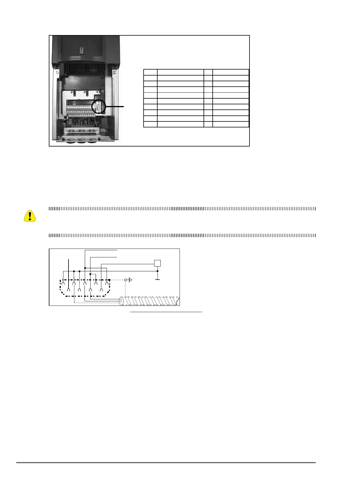
5.4 Serial interface (XS connector)
XS
Function I/O
Electr. interface
PIN1
Internal use
PIN2
Internal use
PIN3
RxA/TxA I/O RS485
PIN4
Equipotentiality (optional)
PIN5
0V (Ground for5V)
–
Power supply
PIN6
Internal use
–
–
PIN7
RxB/TxB I/O RS 485
PIN8
Internal use
PIN9
+5 V
–
Power supply
I=Input
O=Output
The ADV200 SP drive is equipped as standard with a port (9-pin D-SUB receptacle connector: XS) for connec-
-
ration software) or for multi-drop connection.
To access the connector, remove the lower cover as illustrated in shown in paragraph 5.2.1.
5.4.1 Drive / RS 485 Port (not insulated) point-to-point connection
The connection indicated is without galvanic insulation !
Le raccordement indiqué n’a pas d’isolation galvanique !
12
3
45
98 76
TxA/RxA
TxB/RxB
PE
+5 V
XS
Reserved
RS485
EQP
Figure 5.4.1.1: Serial connection (not insulated)
-
kBaud.

 Loading...


