EasyManuals Logo
Home>gefran>DC Drives>ADV200 SP Series

gefran ADV200 SP Series User Manual

gefran ADV200 SP Series
106 pages
To Next Page IconTo Next Page
To Previous Page IconTo Previous Page
Page #28 background imageLoading...
Page #28 background image
28 ADV200 SP • Quick start up guide - Specification and installation
5.2.4 Switches, jumpers and LED
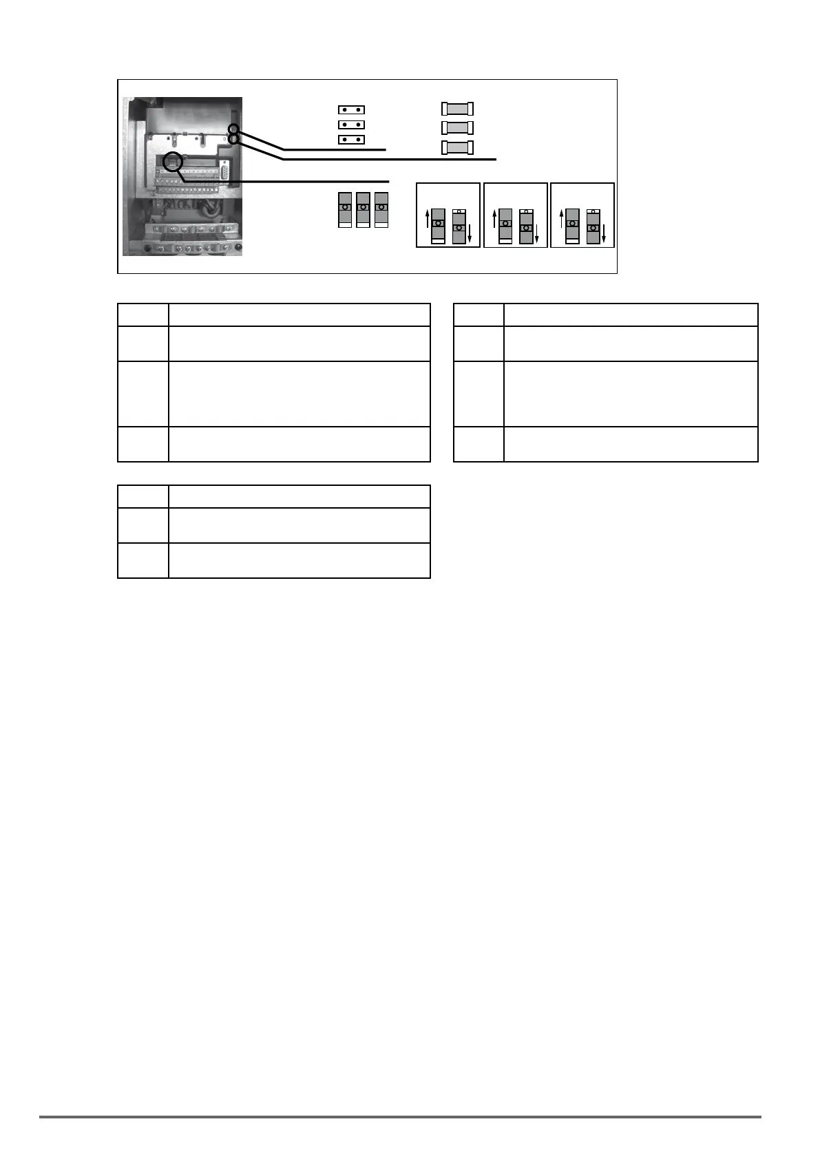
LEDs :
S1 S2 S3
PWM
RUN
PWR
Switches :
S1
Jumpers :
HC0
HC1
CFG
V I
S2
V I
S3
V I
Switch V/I settings on inputs and analog output LEDs Function
S1
Analog input 1
Default = voltage (±10 V)
PWM
(green)
LED lit during IGBT modulation
S2
Analog input 2
Default = voltage (±10 V)
RUN
(green)
Flashes (freq. 1 sec) if no errors or faults have
occurred.
If ON or OFF, indicates an error conditions (software
hangup)
S3
Analog output 2
Default = voltage (±10 V)
PWR
(green)
ON when the regulation card is correctly powered
Jumpers Function
HC0
HC1
Reserved. Deafult = Open
CFG (1)
Open = 400
Vac rated voltage (default) (2)
Closed = 460
Vac rated voltage (3)
threshold

 

Table of Contents

Questions and Answers:

Question and Answer IconNeed help?

Do you have a question about the gefran ADV200 SP Series and is the answer not in the manual?

gefran ADV200 SP Series Specifications

General IconGeneral
Brandgefran
ModelADV200 SP Series
CategoryDC Drives
LanguageEnglish

Related product manuals