36 ADV200 SP • Quick start up guide - Specification and installation
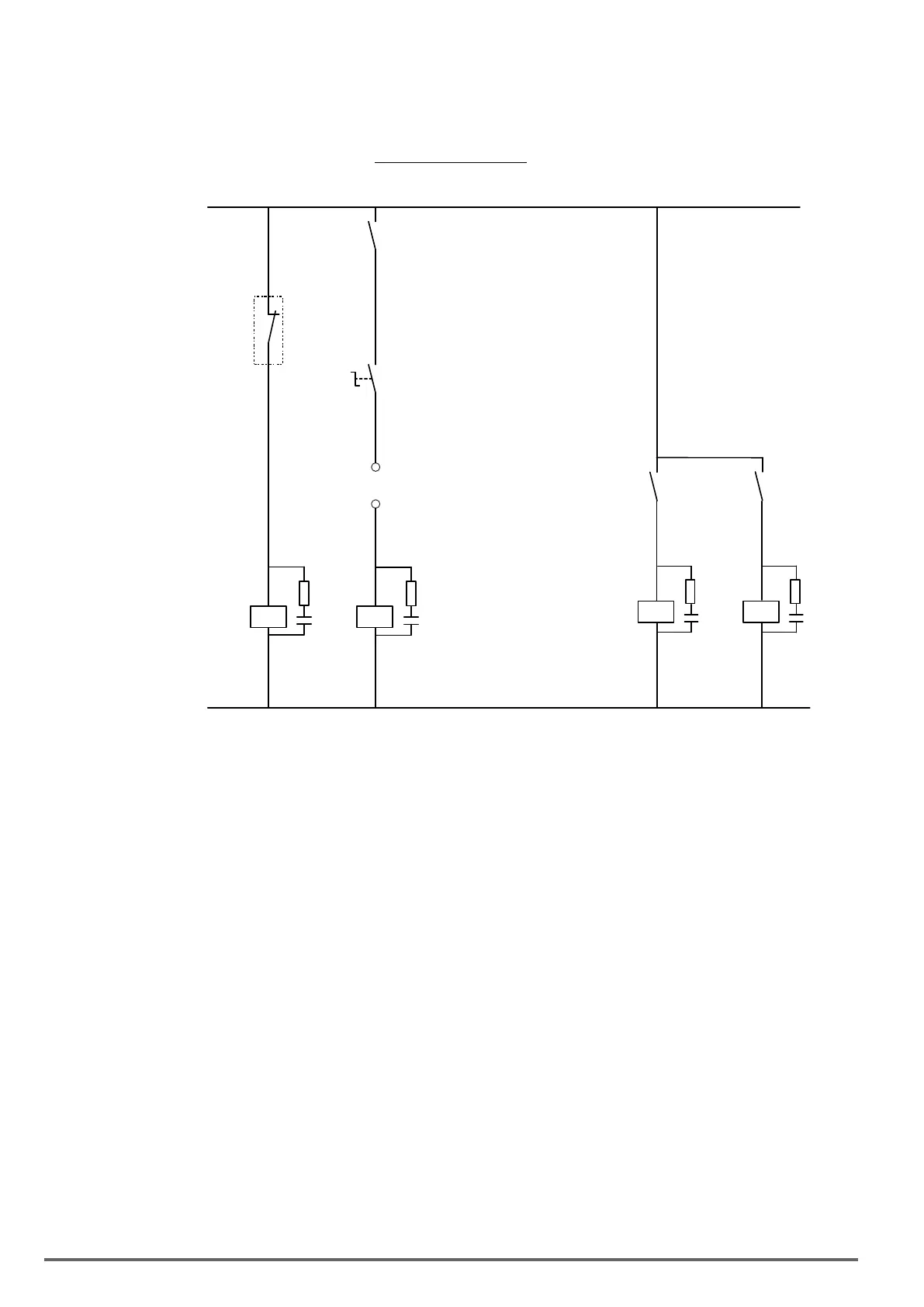
5.5 Typical connection diagrams
The diagrams shown are for example only, in any case the installer must comply with the rules relating to the
state of competence, in order to have a state-of-the-art system.
Figure 5.5.1: Auxiliary control circuits
EMERGENCY-OFF
EMERGENCY-OFF
K0
K0
S1 ON / OFF
ON / OFF
Start / Stop
K2
K4
K1M
Mains
contactor
L01
L00
K2M
K3
PV source
contactor
CM
Push button switch
S1 = Power On Selector
Auxiliary relays
K2 = “Command” relay coil
Power relays
K1M = AC relay coil
K2M = DC relay coil
Other
CM = Run consent
 Loading...


