Figure4.4.71Motoroverloadprotectioncurve(example:standardmotor)
Low Speed
Hot Start
100% 150% 200%
Motor Load Current (%)
(02-01 = 100%)
Overload Protect Time (min)
1.5
2.9
7.9
Low Speed
Cold Start
100% 150% 200%
Motor Load Current (%)
(02-01 = 100%)
Overload Protect Time (min)
2.4
4.5
12.4
(60Hz)
Hot Start
106% 150% 200%
Motor Load Current (%)
(02-01 = 100%)
Overload Protect Time (min)
1.7
3.9
28.8
start activacted point
(60Hz)
Cold Start
106% 150% 200%
Motor Load Current (%)
(02-01 = 100%)
Overload Protect Time (min)
2.7
6.1
45.2
start activacted point
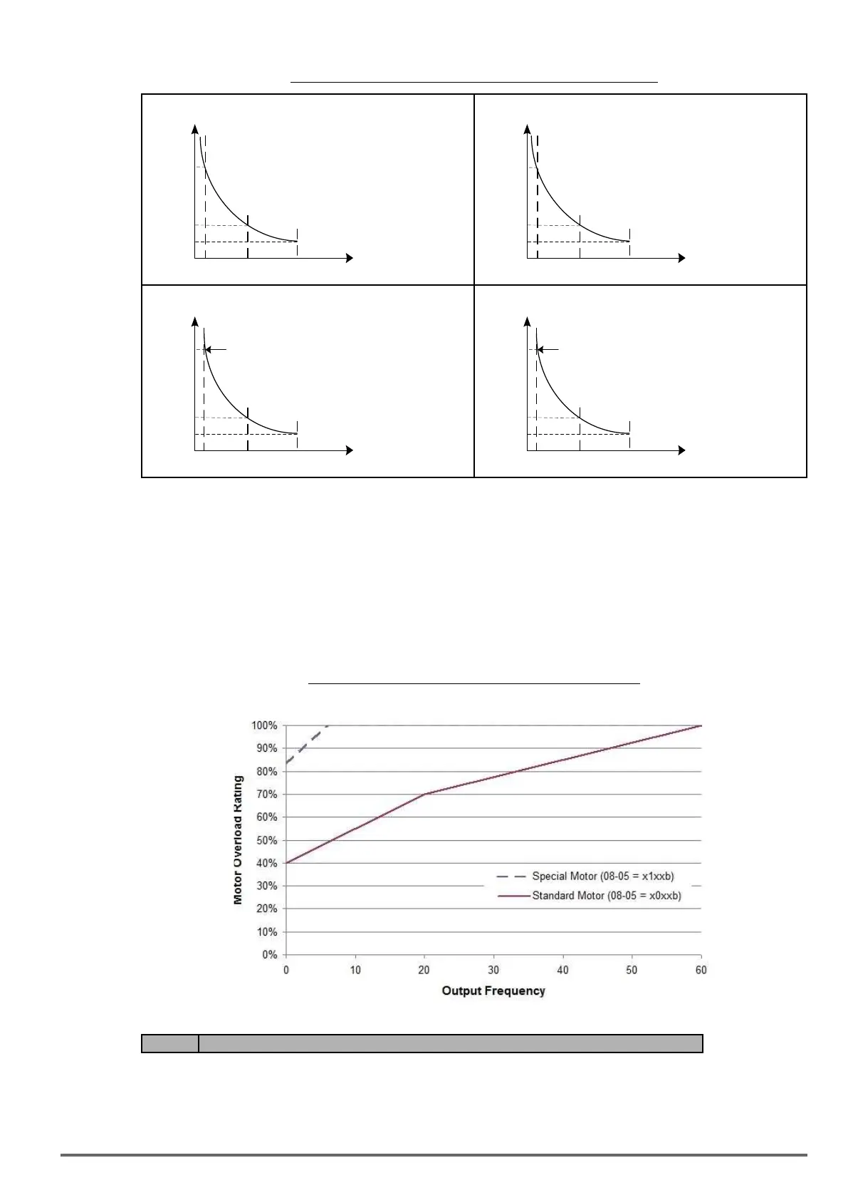
When using force cooled motors (Special inverter motor), thermal characteristics are independent of the motor
speed, set 08-05 = x1xxb.
When 08-05 = x1xxb, overload protection function is based on motor rated current for output frequencies be-
tween 6 and 60Hz. If the output frequency is lower than 1Hz, the overload protection function uses 83% of the
motor rated current to determine an overload condition.
When 08-05 = x0xxb, overload protection function is based on 70% of the motor rated current for an output
frequency of 20Hz. If the output frequency is lower than 1Hz, the overload protection function uses 40% of the
motor rated current to determine an overload condition.
Motor overload rating at different output frequencies is shown at Figure 4.4.72.
Figure4.4.72Motoroverloadratingatdifferentoutputfrequencies
Code Parameter Name / Range
08-06 Start-up mode of overload protection operation (OL1)
0: Stop output after overload protection
1: Continuous operation after overload protection.
08-06=0: When the inverter detects a motor overload the inverter output is turned off and the OL1 fault mes-
VDI100 • Instruction manual 205

 Loading...


