400V Class Models
Model
01-09
Minimum Output
Voltage 1 of Motor 1
01-07
Middle Output
Voltage 1 of Motor 1
01-23
Minimum Output
Voltage 1 of Motor 2
01-21
Middle Output
Voltage 1 of Motor 2
11-59
Gain of Preventing
Oscillation
11-60
Upper Limit of
Preventing Oscillation
1007
1015
15.8V 25.6V 15.8V 25.6V 0.05 100
1022 15.0V 28.0V 15.0V 28.0V 0.05 100
2037
2055
15.0V 28.0V 15.0V 28.0V 0.05 100
3075 15.0V 28.0V 15.0V 28.0V 0.05 100
3110 15.0V 28.0V 15.0V 28.0V 0.05 10
3150
4150
4185
4220
15.0V 28.0V 15.0V 28.0V 0.01 10
5300
5370
5450
17.0V 30.0V 17.0V 30.0V 0.01 10
5550
6750
17.0V 30.0V 17.0V 30.0V 0.01 10
6900
71100
71320
71600
17.0V 30.0V 17.0V 30.0V 0.01 10
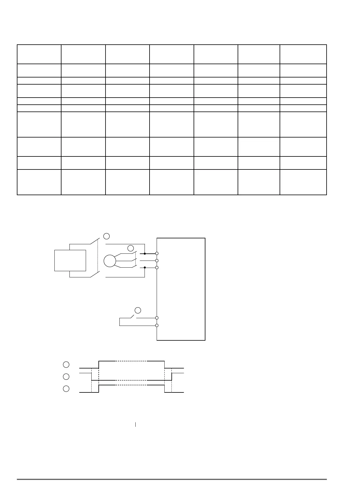
4.3.2. Low Voltage Detection Level Function
R/L1
S/L2
T/L3
3
~
S1~S8
24VG
AC Motor Drive
UPS or
battery
1-Phase UPS or Battery
440V Vac: 207~380
Vdc: 292~537
Execute Low Voltage
Detection Level Input
Notes for the emergency power supply. Please be aware of the following condition
when emergency power is ON:
1. Execute Low Voltage Function ON (DI=62),Fan doesn’t run.
2. Execute Low Voltage Function ON (DI=62),No phase loss.
3. Execute Low Voltage Function ON (DI=62),run frequency of motor depends on
the value of07-31
2
1
2
3
3
Timing Diagram of Magnetic Contactor
Before inputting emergency power, magnetic contactor ①and ③ are ON and
magnetic contactor ② should be OFF. Magnetic contactor ③ should be ON
after magnetic contactor is ON. Before removing battery and turning magnetic
contactor ② to be ON, Magnetic contactor ①and ③ should be OFF.
Wiring:
94 VDI100 • Instruction manual

 Loading...


